Question 2
This question is about waves on wires and in tubes.
a) A uniform wire of length and mass per unit length, , is stretched between two fixed points. A point close to one end is plucked and a pulse travels along the wire at speed , as shown in Fig. 1, to reflect off the right hand fixed end.
(Figure 1: Pulse travelling at speed along a wire under tension.)
(i) Sketch a diagram of the reflected pulse.
(ii) After a second reflection from the left hand end, the pulse would be passing the initial point and travelling in the same direction. At that moment the wire could be plucked again to reinforce the pulse. What is the period of plucking, which would accomplish this?
(iii) Calculate the corresponding frequency of plucking the wire, , in terms of and .
(iv) If a mechanical vibrator is attached to the wire to produce oscillations of frequency (which are the harmonics or multiples of the 1st harmonic, ) what resonant frequencies of the wire will be sustained, in terms of integer , and .
(v) The wire is now plucked near one end whilst a finger is lightly touching the wire at a point 40% of length from one end. Sketch the resultant amplitude of vibration along the wire, and determine the two lowest frequencies heard in terms of .
(vi) The speed of transverse waves along a stretched wire is given by , with the tension in the wire. What would be the tension required in order to sustain the fifth harmonic, , of frequency 162 Hz in the wire if its length is 2.3 m and mass is 42 g.
(6)
b) In this example we hang the cable vertically and use its own weight to provide the tension. A massive, uniform cable of length and mass hangs with its upper end fixed to a support and the lower end free. The extension is negligible.
(i) What is the tension at a distance below the support?
(ii) The cable is shaken slightly at the bottom end. Using the information in part (a)(vi), calculate the ratio of the speeds of the pulse on the cable at points 1/4 of its length from the top end and 1/4 of its length from the bottom end.
(iii) The cable is now plucked at the top end as in Fig. 2 and the pulse travels down the cable. Write an expression for the speed of a pulse travelling down the cable in terms of , and .
(iv) Now obtain an expression for the time taken, for a pulse to travel a distance down the cable from the support at the top end.
(v) At the same moment that the cable is plucked at the top end, a ball is dropped from rest from the same starting height. At what value of in terms of will the ball overtake the pulse traveling down?
(Figure 2: Pulse travelling down a vertical hanging cable.)
(8)
c) The timing of pulses can be used in GPS systems. A stationary receiver is at a point on the line between two radio transmitters which lie on a West-East line, as in Fig. 3. Each transmitter contains a highly accurate clock and broadcasts a precise 1 MHz electromagnetic wave in pulses. After each pulse, a signal is sent with the exact time at which that signal was sent. The radio transmitters are 600 km apart. At the receiver, pulses are received from both transmitters. The pulse from the Western transmitter is received 1542 cycles of the 1 MHz wave before the pulse from the Eastern transmitter is received. The pulse from the Western transmitter was sent 0.000 484 s before the pulse from the Eastern transmitter.
How far is the receiver from the Western transmitter?
(Figure 3: Two transmitters and a receiver lying along a W-E line)
(2)
d) A resonant tube of length is closed at one end and has a small loudspeaker close to the open end as in Fig. 4. An a.c. signal of frequency is supplied to the speaker, and adjusted so the tube resonates at its lowest frequency, . This longitudinal sound wave has a displacement node at the closed end and an antinode at the open end.
(i) Sketch three graphs of the amplitude of the standing wave along the tube, for the lowest three harmonics that can be heard, as the speaker frequency is steadily increased.
(ii) Now in dotted lines but on the same axes as already drawn in part (i), sketch three graphs of the corresponding pressure variation of the air with position along the tube.
(Figure 4: Speaker above the open end of a closed tube.)
(2)
e) The speed of sound in air is given by the equation where is a numeric constant, is the pressure and is the density of the air.
(i) In a 20 m tall vertical tube closed at one end, by how much is the pressure of air greater at the bottom of the tube relative to the top?
(ii) Why is it that the speed of sound does not vary with the depth of the air in the tube?
(iii) However, the speed does depend upon the absolute temperature of the air. Obtain an expression for the dependence on the speed of sound in terms of the constant , the gas constant , the absolute temperature and the kg molar mass in kg mol.
(iv) In a tube closed at one end, the antinode at resonance is located a (small) fixed distance beyond the open end of the tube. This length is known as the end correction and is illustrated in Fig. 5.
A tube closed at one end, of length 52.0 cm, and filled with air at 20.0°C, resonates at its first harmonic at 156 Hz. A second, shorter tube alongside, which has the same end correction, , is filled with warm air at 35°C and resonates at a slightly different frequency, producing beats with the first tube at 4.8 Hz. What is the length of the second tube?
At 20°C the speed of sound in air is 343 m s.
Atmospheric pressure is Pa.
Density of air at atmospheric pressure and 15°C is 1.225 kg m.
(Figure 5: The end correction, for an antinode located above the open end of the tube.)
(7)
[25 marks]
 Fig. 1: pulse on wire under tension
 Fig. 2: pulse down vertical hanging cable
 Fig. 3: two transmitters and receiver W-E line
 Fig. 4: speaker above open end of closed tube
 Fig. 5: end correction antinode above open end
Topic: Oscillations & Waves, Thermodynamics, Newtonian Mechanics Metodi: Wave Equation, Simple Harmonic Motion Analysis, Ideal Gas Law, Calculus-Integration, Kinematic Equations Competenze: Mathematical Modeling, Physical Reasoning, Diagrammatic Reasoning Objects: Wire, Tube, Ball Fonte: Testo (PDF) — p.4
La domanda 2
Questa domanda riguarda le onde su fili e tubi.
a) Un filo uniforme di lunghezza e di massa per unità di lunghezza è esteso tra due punti fissi. Si stacca un punto vicino ad una estremità e un impulso si muove lungo il filo a velocità , come mostrato nella figura. 1, per riflettere l’estremità fissa della mano destra.
(Figura 1: Pulso che viaggia a velocità lungo un filo sotto tensione.)
(i) Segnare un diagramma dell’impulso riflesso.
(ii) Dopo un secondo riflesso dall’estremità sinistra, il polso passerà il punto iniziale e andrà nella stessa direzione. In quel momento il filo poteva essere strappato di nuovo per rafforzare il polso. Qual è il periodo di prelievo, che lo realizzerebbe?
(iii) Calcolare la corrispondente frequenza di stracciamento del filo, , in termini di e .
(iv) Se al filo è attaccato un vibratore meccanico per produrre oscillazioni di frequenza (che sono gli armonici o i multipli del primo armone, ), quali frequenze di risonanza del filo saranno sostenute, in termini di numeri interi , e .
(v) Il filo viene ora strappato vicino ad una estremità mentre un dito tocca leggermente il filo ad un punto del 40% di lunghezza da una estremità. Segnare l’ampiezza di vibrazione risultante lungo il filo e determinare le due frequenze più basse ascoltate in termini di .
(vi) La velocità delle onde trasversali lungo un filo esteso è data da , con la tensione del filo. Qual è la tensione necessaria per sostenere la quinta armonica, , di frequenza 162 Hz nel filo, se la sua lunghezza è di 2,3 m e la sua massa è di 42 g.
(6)
b) In questo esempio appendiamo il cavo verticalmente e utilizziamo il suo peso per fornire la tensione. Un cavo massiccio e uniforme di lunghezza e di massa è appeso con la sua estremità superiore fissata a un supporto e la parte inferiore libera. L’estensione è trascurabile.
(i) Qual è la tensione a una distanza sotto il supporto?
- il cavo è leggermente scosso alla fine inferiore. Con l’aiuto delle informazioni di cui alla parte (a) ((vi), calcolare il rapporto tra le velocità dell’impulso sul cavo nei punti 1/4 della sua lunghezza dall’estremità superiore e 1/4 della sua lunghezza dall’estremità inferiore.
(iii) Il cavo è ora strappato all’estremità superiore come in Figura. 2 e il polso scende lungo il cavo. Scrivere un’espressione per la velocità di un impulso che scende lungo il cavo in termini di , e .
(iv) Ora ottenere un’espressione per il tempo impiegato, per un impulso per viaggiare una distanza lungo il cavo dal supporto in alto.
(v) Allo stesso momento in cui il cavo viene strappato all’estremità superiore, una palla viene abbassata dal riposo dalla stessa altezza di partenza. A quale valore di in termini di la palla supererà il pulso che scende verso il basso?
(Figura 2: Pulso che scende lungo un cavo appeso verticale.)
(8)
c) Il tempo dei pulsi può essere utilizzato nei sistemi GPS. Un ricevitore stazionario si trova in un punto della linea tra due trasmettitori radio che si trovano su una linea ovest-est, come in Figura. 3. Ogni trasmettitore contiene un orologio altamente preciso e trasmette un’onda elettromagnetica di 1 MHz in pulsi. Dopo ogni pulso, viene inviato un segnale con l’esatto momento in cui è stato inviato. I trasmettitori radio sono a 600 km di distanza. Al ricevitore vengono ricevuti impulsi da entrambi i trasmettitori. Il pulso del trasmettitore occidentale viene ricevuto 1542 cicli di onde di 1 MHz prima che venga ricevuto il pulso del trasmettitore orientale. L’impulso del trasmettitore occidentale è stato inviato 0,000 484 secondi prima dell’impulso del trasmettitore orientale.
Quanto è lontano il ricevitore dal trasmettitore occidentale?
(Figura 3: Due trasmettitori e un ricevitore lungo una linea W-E)
(2)
d) Un tubo di risonanza di lunghezza è chiuso ad una estremità e dispone di un piccolo altoparlante vicino all’estremità aperta, come in Figura 1. 4. An a.c. il segnale di frequenza viene fornito al altoparlante e regolato in modo che il tubo risonasse alla sua frequenza più bassa, . Questa onda sonora longitudinale ha un nodo di spostamento all’estremità chiusa e un antinodo all’estremità aperta.
(i) Segnare tre grafici dell’amplitudine dell’onda in piedi lungo il tubo, per i tre armonici più bassi che possono essere sentiti, poiché la frequenza del altoparlante aumenta costantemente.
- Ora, in linee puntate, ma sugli stessi assi già disegnati nella parte (i), disegnare tre grafici della corrispondente variazione di pressione dell’aria con la posizione lungo il tubo.
(Figura 4: altoparlante sopra l’estremità aperta di un tubo chiuso.)
(2)
e) La velocità del suono nell’aria è data dall’equazione , dove è una costante numerica, è la pressione e è la densità dell’aria.
(i) In un tubo verticale alto 20 m chiuso da un lato, quanto è maggiore la pressione dell’aria al fondo del tubo rispetto alla parte superiore?
(ii) Perché la velocità del suono non varia con la profondità dell’aria nel tubo?
- la velocità dipende dalla temperatura assoluta dell’aria. Ottenere un’espressione della dipendenza dalla velocità del suono in termini di costante , costante del gas , temperatura assoluta e massa molare di kg in kg mol .
(iv) In un tubo chiuso ad una estremità, l’antinodo a risonanza si trova a una (piccola) distanza fissa oltre l’estremità aperta del tubo. Questa lunghezza è nota come correzione finale e è illustrata nella figura. 5.
Un tubo chiuso da un’altra parte, di lunghezza 52,0 cm, e riempito di aria a 20.0°C, risona al suo primo armonico a 156 Hz. Un secondo tubo più breve, che ha la stessa correzione terminale, , è riempito di aria calda a 35°C e risona a una frequenza leggermente diversa, producendo battiti con il primo tubo a 4,8 Hz. Qual è la lunghezza del secondo tubo?
A 20°C la velocità del suono nell’aria è di 343 m s.
La pressione atmosferica è Pa.
La densità dell’aria a pressione atmosferica e 15°C è di 1,225 kg m.
(Figura 5: Correzione finale, per un antinodo situato sopra l’estremità aperta del tubo.)
(7)
[25 punti]
Fig. 1: impulso sul filo sotto tensione
Fig. 2: pulsazione verso il basso del cavo appeso verticale
Fig. 3: due trasmettitori e ricevitore W-E line
Fig. 4: altoparlante sopra l’estremità aperta del tubo chiuso
Fig. 5: correzione finale antinodo sopra la fine aperta
Topic: Oscillations & Waves, Thermodynamics, Newtonian Mechanics Metodi: Wave Equation, Simple Harmonic Motion Analysis, Ideal Gas Law, Calculus-Integration, Kinematic Equations Competenze: Mathematical Modeling, Physical Reasoning, Diagrammatic Reasoning Objects: Wire, Tube, Ball Fonte: Testo (PDF) — p.4
Question 3
This question is about the properties of some electrical circuits.
a) The circuit in Fig. 6 shows a chain of identical resistors of value 4.0 Ω. A current of 1.0 A flows through the final resistor.
(i) What is the potential difference across AB?
(ii) What is the equivalent resistance of the chain?
(Figure 6)
(2)
b) A rechargeable cell, modelled as an emf in series with an internal resistance , has a current of 0.5 A flowing when a charging potential of 2.5 V is applied. When discharged through a 7.6 Ω resistor, a current of 0.25 A flows.
Determine the emf and internal resistance of the cell.
(3)
c) A cell of emf is connected to a resistor that is in series with a pair of resistors and as shown in Fig. 7.
(Figure 7)
(i) For the two resistors and in parallel, show that an expression for the equivalent resistance, can be written in the form .
(ii) If a current was flowing through ,
i. what fraction of would flow through , and
ii. give an expression for the current through in terms of , , and .
(2)
We can use this information to analyse a circuit with more than one source of emf.
(iii) A simple circuit consisting of two cells in series with a resistor is shown in Fig. 8.
(Figure 8: Two cells in series with a resistor.)
i. If cell was removed and points Y and Z joined, what would be the current now in the circuit?
ii. If cell was removed instead, and points X and Y joined, what would be the current now in the circuit?
(1)
If the two cells are both in the circuit, you can see how each source of emf contributes to the current flow. They can be added linearly to give the total current flow.
The circuit shown in Fig. 9 consists of two cells and connected to resistors , and .
(iv) Remove cell and connect the break in the circuit. Using the notation of this circuit, write down the current flow through .
(v) Replace cell and remove cell , connecting the circuit at the break. Write down the current flow through .
(vi) By linearity, . Write down an expression for in terms of , , , and .
(3)
(Figure 9: Two cells and three resistors in a circuit.)
(vii) This circuit can also be viewed as two cells in parallel, each with an internal resistance, connected to an external load resistor . By considering values of or otherwise, show that the cells in parallel behave as a source of emf given by
and internal resistance
(viii) Using this result, if V, V, and , calculate
i. the value of that will dissipate maximum power in (this occurs when the load resistor is equal to the internal resistance of the supply), and
ii. determine the value of the maximum power in .
iii. If the resistance of is increased, one cell will begin to charge the other. At what value of does this begin to occur?
(6)
d) Circuits with non-linear components are of great importance. The following circuit of Fig. 10 resembles ones just analysed, but its behaviour is different. The circuit is designed to prevent damage to the device represented by the 10 kΩ load resistor when the circuit is suddenly connected to a 2000 V d.c. supply. The component S is a voltage suppressor, which has a V–I characteristic given by , where is the voltage across S when current flows through it. The constant has a value A V.
(i) What is the value of the current in the 10 kΩ load resistor when operating normally?
(ii) A surge in the supply voltage causes the current in the load resistor to double from its normal value. What is the value of the surge voltage from the supply?
(Figure 10: A circuit with a voltage suppressor S and a 10 kΩ load resistor.)
(8)
[25 marks]
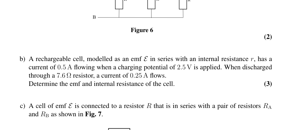 Fig. 6: chain of identical 4 Ω resistors
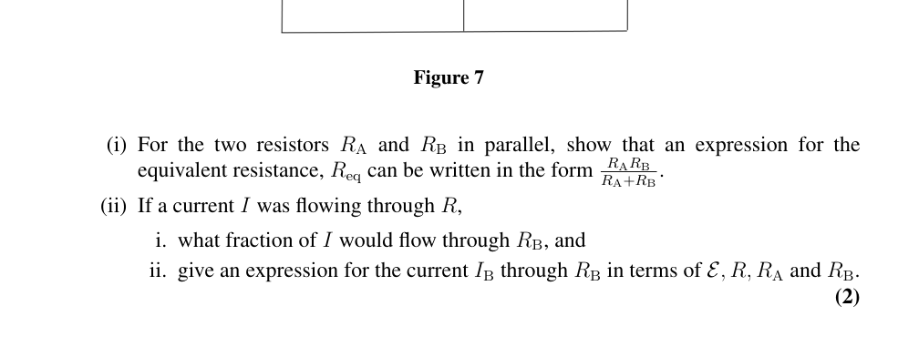 Fig. 7: cell E with R in series with parallel RA and RB
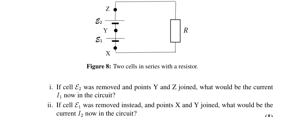 Fig. 8: two cells in series with a resistor
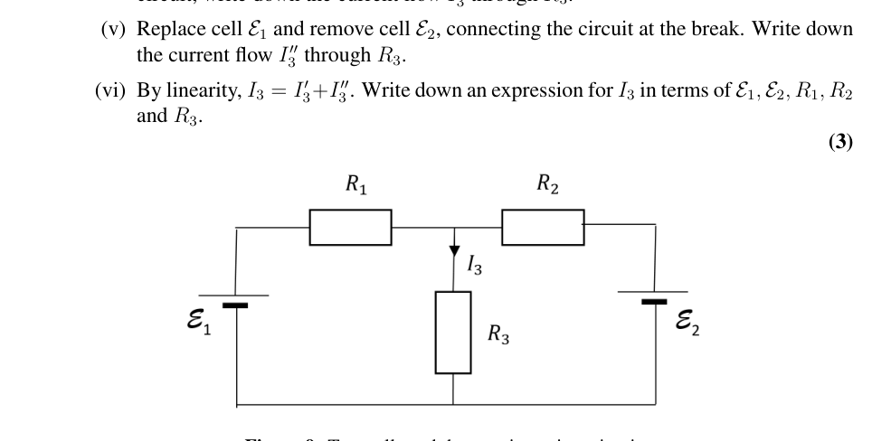 Fig. 9: two cells and three resistors circuit
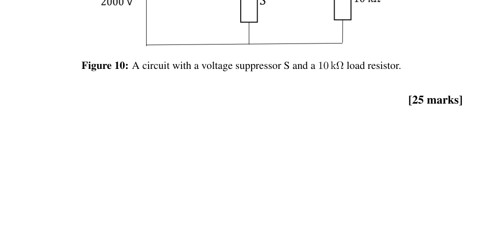 Fig. 10: voltage suppressor S and 10 kΩ load resistor
Topic: Circuits, Electrostatics Metodi: Kirchhoff’s Laws, Equivalent Circuit Reduction, Superposition Principle, Physical Modeling Competenze: Mathematical Modeling, Physical Reasoning Objects: Resistor, Battery Fonte: Testo (PDF) — p.7
La domanda 3
Questa domanda riguarda le proprietà di alcuni circuiti elettrici.
a) Il circuito di Fig. 6 mostra una catena di resistenti identici di valore 4,0 Ω. Una corrente di 1,0 A scorre attraverso la resistenza finale.
(i) Qual è la differenza potenziale tra gli AB?
(ii) Qual è la resistenza equivalente della catena?
(Figura 6)
(2)
b) Una cella ricaricabile, modellata come emf in serie con resistenza interna , ha una corrente di 0,5 A che scorre quando viene applicato un potenziale di ricarica di 2,5 V. Quando viene scaricato attraverso una resistenza di 7,6 Ω, scorre una corrente di 0,25 A.
Determina l’emf e la resistenza interna della cellula.
(3)
c) Una cella di emf è collegata a una resistenza che è in serie con una coppia di resistenze e come mostrato nella figura. 7.
(Figura 7)
(i) Per le due resistenze e in parallelo, dimostrare che un’espressione per la resistenza equivalente, può essere scritta nella forma .
(ii) Se una corrente scorreva attraverso ,
i. quale frazione di fluirà attraverso , e
ii. indicare l’espressione per la corrente passando da in termini di , , e .
(2)
Possiamo usare queste informazioni per analizzare un circuito con più di una fonte di emf.
(iii) Un circuito semplice costituito da due celle in serie con resistenza è mostrato nella figura. 8.
(Figura 8: Due cellule in serie con resistenza.)
i. Se la cella fosse rimossa e i punti Y e Z fossero uniti, quale sarebbe la corrente attuale nel circuito?
ii. Se invece la cella fosse rimossa e i punti X e Y fossero uniti, quale sarebbe la corrente attuale nel circuito?
(1)
Se entrambe le cellule sono nel circuito, si può vedere come ciascuna fonte di emf contribuisce al flusso corrente. Possono essere aggiunte in modo lineare per dare il flusso totale di corrente.
Il circuito mostrato in Figura 1. 9 è costituito da due celle e collegate alle resistenze , e .
(iv) Rimuovere la cellula e collegare la rottura nel circuito. Utilizzando la notazione di questo circuito, annotare il flusso di corrente attraverso .
(v) Rimpiazzare la cella e rimuovere la cella , collegando il circuito alla rottura. Scrittore del flusso corrente attraverso .
(vi) Per linearità, . Scrivere un’espressione per in termini di , , , e .
(3)
(Figura 9: Due celle e tre resistori in un circuito.)
(vii) Questo circuito può essere anche visto come due celle parallele, ciascuna con una resistenza interna, collegata ad una resistenza esterna al carico . Considerando valori di o altrimenti, dimostrare che le celle in parallelo si comportano come fonte di emf data da
e resistenza interna
(viii) Usando questo risultato, se V, V, e , calcolare
i. il valore di che dissiperà la potenza massima in (questo si verifica quando la resistenza al carico è uguale alla resistenza interna dell’alimentazione); e
ii. determinare il valore della potenza massima in .
iii. Se la resistenza di è aumentata, una cellula inizierà a caricare l’altra. A quale valore di si verifica?
(6)
d) I circuiti con componenti non lineari sono di grande importanza. Il circuito seguente di Fig. 10 assomiglia a quelli appena analizzati, ma il suo comportamento è diverso. Il circuito è progettato per evitare danni al dispositivo rappresentato dalla resistenza a carico da 10 kΩ quando il circuito è improvvisamente collegato a un 2000 V d.c. fornitura. Il componente S è un soppressore di tensione, che ha una caratteristica VI data da , dove è la tensione attraverso S quando la corrente fluisce attraverso di esso. La costante ha un valore A V.
(i) Qual è il valore della corrente nella resistenza a carico di 10 kΩ quando funziona normalmente?
- un aumento della tensione di alimentazione fa sì che la corrente della resistenza al carico raddoppi il suo valore normale. Qual è il valore della tensione di surriscaldamento dell’alimentazione?
(Figura 10: Circuito con soppressore di tensione S e resistenza a carico di 10 kΩ.)
(8)
[25 punti]
Fig. 6: catena di resistori 4 Ω identici
Fig. 7: cellula E con R in serie con RA e RB paralleli
Fig. 8: due celle in serie con resistenza
Fig. 9: circuito a due celle e tre resistori
Fig. 10: soppressore di tensione S e resistenza a carico di 10 kΩ
Topic: Circuits, Electrostatics Metodi: Kirchhoff’s Laws, Equivalent Circuit Reduction, Superposition Principle, Physical Modeling Competenze: Mathematical Modeling, Physical Reasoning Objects: Resistor, Battery Fonte: Testo (PDF) — p.7
Question 4
This question is about electric fields.
a) A capacitor C consists of two parallel conducting plates, of large area , separated by a distance . A charge is applied to one plate and to the other, as shown in Fig. 11.
(i) Sketch three diagrams, showing the electric field due to one plate alone, the electric field due to the other plate alone, and the resultant electric field when both plates are in place parallel to each other. Neglect edge effects where the field may be non-uniform at the edges of the plates.
(ii) Both plates are now positively charged, each with instead. Sketch the three corresponding diagrams of the fields as in part (i).
(iii) The energy of a and charged capacitor can be written in terms of and . Given , and considering the work done in separating the charged plates by , derive an expression for the force acting between the plates in terms of , and .
(iv) Write down an expression for the field strength between the plates in terms of and , where .
(v) If the area of the plates is doubled, by what factor is changed to maintain the same force?
(vi) A thunder cloud forms over a large area of still water. What is the electrostatic surface charge density on the water if it rises under the cloud to a height 1.5 mm above its previous level?
(8)
b) A point charge produces a radial electric field, at distance from the charge. The same field strength is obtained at the surface of a sphere of radius if the charge is spread uniformly over the surface, with an area charge density .
(i) A conducting sphere of radius is charged to a potential . Write down an expression for the charge on the surface in terms of , and .
Two spheres A and B of radii and respectively are located with a distance between their centres, with , as in Fig. 12. Each sphere is at the same potential .
(Figure 12: Two charged spheres at the same potential.)
(ii) How are the electric field strengths at the surfaces of A and B, and related to each other?
(iii) An ion of charge is released from a point 3.0 mm from the surface of B. If B has a radius of 1.0 mm and is at a potential of 2.0 kV, calculate the energy in electron-volts gained by the ion in moving 1.0 mm towards B.
A pear shaped conducting shell with hemispherical ends, as in Fig. 13, is of circular cross section perpendicular to its longitudinal axis. It is positively charged to a potential .
(Figure 13)
(iv) Copy the diagram and sketch the pattern of electric field lines near the surface of the conductor.
As the potential is raised, the electric field strength at the surface will increase. The air becomes conducting when an electron is accelerated by the E field so that it gains enough energy between collisions to ionise the next atom with which it collides.
(v) If the ionisation energy is 2.5 eV and the mean free path between collisions is m, calculate the electric field strength which will cause the air to break down.
(vi) The radii of the two ends of the shell are 15.0 cm and 5.0 cm. What is the maximum potential of the shell such that it will not discharge through breakdown of the surrounding air?
(vii) Sketch the charge distribution over the surface of the shell.
(10)
c) A point charge is located a perpendicular distance from a large area, thin, earthed, conducting plate, as shown in Fig. 14.
(i) Sketch the field lines linking the point charge and the conducting plane.
(ii) Explain
i. why there is a force acting on the plate,
ii. in which direction is the force on the plate, and
iii. why the force vector acting on the plate is along the direction and passes through the charge .
(iii) Consider the idea of removing the positive charge on the left and placing a negative charge on the right of the plate at distance .
i. Sketch the field lines between the earthed plate and the negative charge.
ii. Now, by considering these field line patterns, with and without the plate present, calculate the attractive force between a C charge located 20 cm from a large, conducting, earthed plate.
(Figure 14: Point charge near a plane conducting plate.)
(7)
[25 marks]
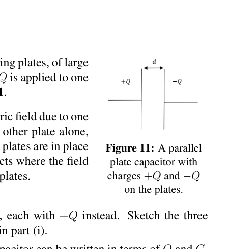 Fig. 11: parallel plate capacitor charges +Q and -Q
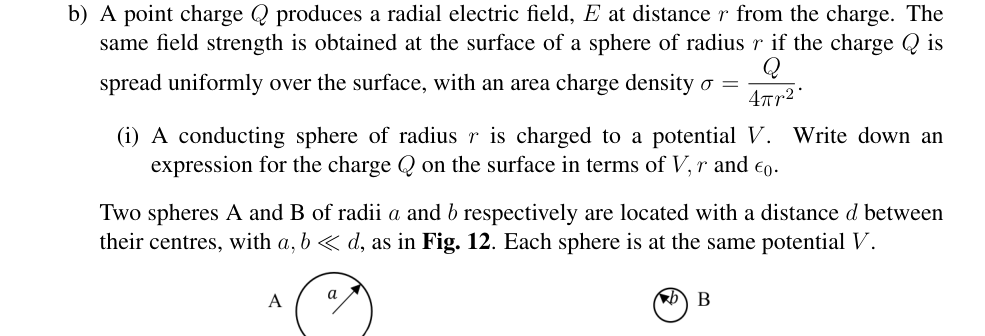 Fig. 12: two charged spheres A and B at same potential
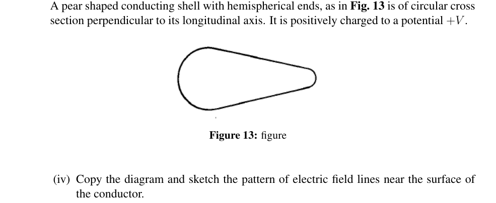 Fig. 13: pear-shaped conducting shell
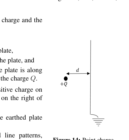 Fig. 14: point charge near earthed conducting plate
Topic: Electrostatics, Electromagnetism Metodi: Gauss’s Law, Electric Potential Method, Coulomb’s Law, Energy Conservation Method Competenze: Mathematical Modeling, Physical Reasoning, Diagrammatic Reasoning Objects: Capacitor, Point Charge, Conducting Sphere Fonte: Testo (PDF) — p.10
La domanda 4
Questa domanda riguarda i campi elettrici.
a) Un condensatore C è costituito da due piastre conduttrici parallele, di grande superficie , separate da una distanza . Si applica una carica su una piastra e sull’altra, come mostrato alla figura. 11.
(i) Segnare tre schemi che mostrino il campo elettrico dovuto ad una sola piastra, il campo elettrico dovuto all’altra piastra e il campo elettrico risultante quando entrambe le piastre sono in posizione parallela l’una all’altra. Negli effetti di bordo quando il campo può essere non uniforme ai bordi delle lastre.
(ii) Entrambe le piastre sono ora cariche positivamente, ognuna con invece. Segnare i tre diagrammi corrispondenti dei campi come nella parte (i).
(iii) L’energia di un condensatore carico e può essere scritta in termini di e . Considerando , e considerando il lavoro svolto per separare le placche cariche da , si deriva un’espressione per la forza che agisce tra le placche in termini di , e .
(iv) Scrivere un’espressione per la resistenza del campo tra le piastre in termini di e , dove .
(v) Se l’area delle lastre è raddoppiata, con quale fattore viene modificato il per mantenere la stessa forza?
(vi) Si forma una nuvola di tuoni su una vasta area di acqua ferma. Qual è la densità di carica elettrostatica della superficie dell’acqua se si eleva sotto la nuvola a 1,5 mm di altezza superiore al suo livello precedente?
(8)
b) Una carica puntaria produce un campo elettrico radial, a distanza dalla carica. La stessa forza di campo è ottenuta sulla superficie di una sfera di raggio se la carica è distribuita uniformemente sulla superficie, con una densità di carica di superficie .
(i) Una sfera conduttrice di raggio è caricata a un potenziale . Scrivere un’espressione per la carica sulla superficie in termini di , e .
Due sfere A e B di raggio e sono situate rispettivamente con una distanza tra i loro centri, con , come in Figura. 12. Ogni sfera è allo stesso potenziale .
(Figura 12: Due sfere cariche con lo stesso potenziale.)
(ii) Come si correlazionano le forze di campo elettrico delle superfici di A e B, e ?
- un ione di carica viene rilasciato da un punto di 3,0 mm dalla superficie di B. Se B ha un raggio di 1,0 mm e ha un potenziale di 2,0 kV, calcolare l’energia in elettron-volti ottenuta dall’ion in movimento di 1,0 mm verso B.
Una conchiglia conduttrice a forma di pera con le estremità emisferiche, come in Figura. 13, è di sezione incrociata circolare perpendicolare al suo asse longitudinale. È caricato positivamente a un potenziale .
(Figura 13)
(iv) Copia il diagramma e disegna il modello di linee di campo elettrico vicino alla superficie del conduttore.
Con l’aumento del potenziale, la forza del campo elettrico in superficie aumenterà. L’aria diventa conduttrice quando un elettrone viene accelerato dal campo E in modo che guadagna energia sufficiente tra collisioni per ionizzare il prossimo atomo con cui colpisce.
(v) Se l’energia di ionizzazione è di 2,5 eV e il percorso libero medio tra collisioni è m, calcolare la forza del campo elettrico che causerà la rottura dell’aria.
(vi) I raggi delle due estremità della conchiglia sono di 15,0 cm e 5,0 cm. Qual è il massimo potenziale del guscio in modo tale che non si scarica attraverso la rottura dell’aria circostante?
(vii) Segnare la distribuzione delle cariche sulla superficie della conchiglia.
(10)
c) Una carica puntaria si trova a una distanza perpendicolare da una grande superficie, sottile, terra, piastra conduttrice, come mostrato alla figura. 14.
(i) Segnare le linee di campo che collegano la carica puntaria e il piano conduttore.
(ii) Spiegare
i. perché c’è una forza che agisce sul piatto,
ii. in quale direzione è la forza sulla targa, e
iii. perché il vettore di forza che agisce sulla piastra è lungo la direzione e passa attraverso la carica .
-
Considerare l’idea di rimuovere la carica positiva sulla sinistra e di posizionare una carica negativa sulla destra della targa a distanza .
i. Sceglierete le linee di campo tra la piastra arrotondata e la carica negativa.
ii. Ora, considerando questi modelli di linea di campo, con e senza la piastra presente, calcolare la forza di attrazione tra una carica C situata a 20 cm da una grande piastra conduttiva e arrotondata.
(Figura 14: carica di punto vicino a una piastra di conduttore aereo.)
(7)
[25 punti]
Fig. 11: cariche parallele del condensatore di piastra +Q e -Q
Fig. 12: due sfere cariche A e B con lo stesso potenziale
Fig. 13: conchiglia conduttrice a forma di pera
Fig. 14: carica a punto vicino alla piastra conduttiva arrotondata
Topic: Electrostatics, Electromagnetism Metodi: Gauss’s Law, Electric Potential Method, Coulomb’s Law, Energy Conservation Method Competenze: Mathematical Modeling, Physical Reasoning, Diagrammatic Reasoning Objects: Capacitor, Point Charge, Conducting Sphere Fonte: Testo (PDF) — p.10
Question 5
This question is about springs and forces.
a) (i) A vertical spring of unstretched length and spring constant is fixed to a rigid support, as in Fig. 15. A mass is attached and the equilibrium length is then .
i. The mass is displaced by a small distance downwards from its equilibrium position. Draw a diagram of the mass and mark on the forces acting.
ii. Referring to your forces diagram, show that the period of oscillation is given by
(Figure 15: Mass hanging from a spring.)
(2)
(ii) Two identical springs each of unstretched length are attached to walls a distance apart, and attached at the centre to a mass , as shown in Fig. 16. The mass rests on a smooth, horizontal plane. Each spring has a spring constant , and can be compressed or stretched.
i. Draw a diagram showing the forces acting on the mass when it is displaced from its equilibrium position by an amount along the line of the springs.
ii. What would be the period of oscillation of the mass when released?
(Figure 16: Two springs attached to a mass, which rests on a smooth horizontal plane.)
(2)
(iii) The walls are now moved apart so that they are separated by distance , with the same springs and mass attached, as in Fig. 17.
i. On a diagram of the mass, mark on the forces acting on the mass when it is displaced by from its equilibrium position.
ii. What is the period of oscillation, , now?
(Figure 17: Two identical springs attached to a mass, which rests on a smooth horizontal plane.)
(1)
(iv) Two springs, each of unstretched length , but with different spring constants and , are attached to a mass and are stretched between the two walls a distance apart, as in Fig. 18. By making a small displacement of the mass from equilibrium, obtain the equation for its period of oscillation .
(Figure 18: Two springs attached to a mass, which rests on a smooth horizontal plane.)
(2)
b) (i) Masses and resting on a smooth horizontal surface are attached to the ends of a light inextensible string of length . When set in rotation they rotate about a point on the string at angular speed . Obtain an expression for the tension in the string in terms of , , and .
(ii) A light spring of constant in compression and extension, has masses and attached to the ends, as shown in Fig. 19. When disturbed the masses oscillate along the line of the spring. The system can be modelled as two springs with a non-oscillating point. Find a function of the masses , such that the period of oscillation can be expressed in the form .
(Figure 19: Two masses attached to a spring on a smooth horizontal surface.)
(4)
c) The graph shown in Fig. 20 illustrates the deceleration of a projectile as it hits the ground.
(i) From the graph, using the average decelerations, make simple estimates of the changes in speed in each of the four deceleration regions as it comes to rest, and determine the initial speed of the projectile.
(ii) Similarly, assuming a uniform change in speed with time in each of the four regions of the graph, estimate the depth of penetration of the projectile into the ground.
(Figure 20: The deceleration profile of a projectile hitting the ground at high speed.)
(5)
d) Approximations and making a simple model are key to doing physics. Often we require linear behaviour in our model, often associated with a small displacement from equilibrium, and also that the collision time is short compared to any other motion of the system. This we can see in the following example.
In a ballistic experiment, a bullet of mass g is fired horizontally at a speed of 320 m s into a rigid container of sand that is fixed to a steel framework, whose sides are represented by very strong, light springs, as shown in Fig. 21. The steel framework together with the box has a mass of kg and when tested, the steel frame deflects 5.0 mm when a force of 200 N is applied horizontally.
What is the maximum deflection of the frame when the bullet is fired into the sand?
(Figure 21: A sandbox attached to a stiff steel framework represented by stiff springs, with an approaching bullet.)
(4)
e) The approximations mentioned above can also be seen in this example.
A steel ball bearing of mass g is dropped from rest from a height of m. It rebounds off a steel cylinder of mass kg which is supported by a light spring of spring constant N m, as shown in Fig. 22.
If the collision between the ball bearing and the cylinder is elastic,
(i) what would be the speed of the cylinder immediately after impact, and
(ii) what would be the maximum deflection of the spring?
(Figure 22: A steel cylinder supported by a light spring.)
You may find it helpful to use the ratio of the masses, .
(iii) If the collision is not elastic, then we need to have another measurement. Now the cylinder deflects by 12.0 mm from its equilibrium position as a result of the collision. Calculate the height of rebound of the ball.
(5)
[25 marks]
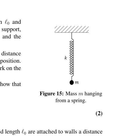 Fig. 15: mass m hanging from a vertical spring
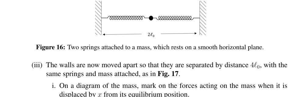 Fig. 16: two springs attached to mass on horizontal plane
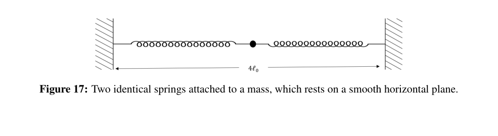 Fig. 17: two springs at 4l0 separation attached to mass
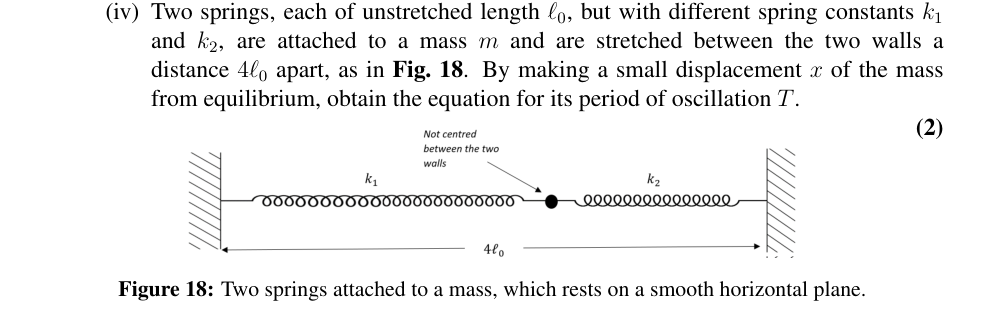 Fig. 18: two springs with different k1 k2 and mass
 Fig. 19: two masses on spring horizontal surface
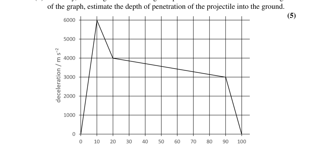 Fig. 20: deceleration profile of projectile hitting ground
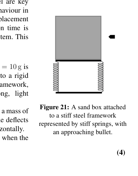 Fig. 21: sandbox on steel framework with approaching bullet
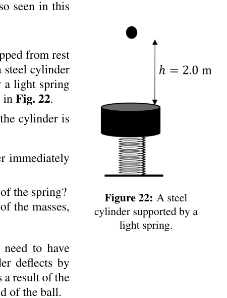 Fig. 22: steel cylinder on light spring
Topic: Oscillations & Waves, Newtonian Mechanics, Conservation of Momentum Metodi: Simple Harmonic Motion Analysis, Hooke’s Law, Conservation of Momentum, Conservation of Energy, Free-Body Diagram, Experimental Data Analysis Competenze: Mathematical Modeling, Physical Reasoning, Diagrammatic Reasoning Objects: Spring, String, Projectile, Cylinder, Ball Fonte: Testo (PDF) — p.12
La domanda 5
Questa domanda riguarda le sorgenti e le forze.
a) (i) Una molla verticale di lunghezza non allungata e costante di molla è fissata a un supporto rigido, come in Figura. 15. Si attacca una massa e la lunghezza di equilibrio è quindi .
i. La massa è spostata da una piccola distanza verso il basso dalla sua posizione di equilibrio. Disegna un diagramma della massa e segna le forze che agiscono.
ii. In riferimento al diagramma delle forze, mostrare che il periodo di oscillazione è dato da
(Figura 15: massa appesa a una sorgente).
(2)
ii) Due sorgenti identiche di lunghezza non allungata sono fissate alle pareti a distanza e fissate al centro ad una massa , come mostrato alla figura. 16. La massa si posa su un piano liscio e orizzontale. Ogni molla ha una costante di molla , e può essere compressa o allungata.
i. Disegnare un diagramma che mostri le forze che agiscono sulla massa quando essa viene spostata dalla sua posizione di equilibrio da una quantità lungo la linea delle molle.
ii. Qual sarà il periodo di oscillazione della massa quando sarà rilasciata?
(Figura 16: Due sorgenti attaccate a una massa, che si riposa su un piano orizzontale liscio.)
(2)
-
le pareti sono ora spostate in modo che siano separate da una distanza , con le stesse sorgenti e la stessa massa fissate, come in Figura. 17.
i. Su un diagramma della massa, segna le forze che agiscono sulla massa quando essa è spostata da dalla sua posizione di equilibrio.
ii. Qual è il periodo di oscillazione, , ora?
(Figura 17: Due sorgenti identiche attaccate a una massa, che si riposa su un piano orizzontale liscio.)
(1)
(iv) Due sorgenti, ciascuna di lunghezza non allungata , ma con costanti di sorgente diverse e , sono attaccate a una massa e si allungano tra le due pareti a distanza , come riportato nella figura. 18. Con un piccolo spostamento della massa dall’equilibrio, si ottiene l’equazione per il suo periodo di oscillazione .
(Figura 18: Due sorgenti attaccate a una massa, che si posa su un piano orizzontale liscio.)
(2)
b) i) Masse e che si appoggiano su una superficie orizzontale liscia sono attaccate alle estremità di una stringa di lunghezza che non si estende a leggero. Quando sono impostate in rotazione, ruotano circa un punto della corda a velocità angolare . Ottenere un’espressione della tensione nella stringa in termini di , , e .
(ii) Una sorgente leggera di costante di compressione ed estensione, ha masse e attaccate alle estremità, come mostrato alla figura. 19. Quando sono disturbate le masse oscilano lungo la linea della sorgente. Il sistema può essere modellato come due molle con un punto non oscillante. Trovare una funzione delle masse , tale da poter esprimere il periodo di oscillazione nella forma .
(Figura 19: Due masse attaccate a una sorgente su una superficie orizzontale liscia.)
(4)
c) Il grafico riportato nella figura. 20 illustra il rallentamento di un proiettile quando colpisce il terreno.
-
a partire dal grafico, utilizzando le decelerazioni medie, effettuare semplici stime dei cambiamenti di velocità in ciascuna delle quattro regioni di decelerazione in quanto si tratta di riposo e determinare la velocità iniziale del proiettile.
-
Allo stesso modo, assumendo un cambiamento uniforme della velocità con il tempo in ciascuna delle quattro regioni del grafico, stimare la profondità di penetrazione del proiettile nel terreno.
(Figura 20: Profil di decelerazione di un proiettile che colpisce il terreno ad alta velocità.)
(5)
d) Gli approcci e la realizzazione di un modello semplice sono fondamentali per fare la fisica. Spesso richiediamo un comportamento lineare nel nostro modello, spesso associato a un piccolo spostamento dall’equilibrio, e anche che il tempo di collisione sia breve rispetto a qualsiasi altro movimento del sistema. Questo si può vedere nell’esempio seguente.
In un esperimento balistico, un proiettile di massa g viene sparato orizzontalmente a una velocità di 320 m s in un contenitore rigido di sabbia fissato a una struttura in acciaio, i cui lati sono rappresentati da sorgenti leggere molto forti, come mostrato nella figura. 21. Il telaio in acciaio, insieme alla scatola, ha una massa di kg e, quando viene testato, il telaio in acciaio devierà di 5,0 mm quando viene applicata orizzontalmente una forza di 200 N.
Qual è la deviazione massima del telaio quando il proiettile viene sparato nella sabbia?
(Figura 21: una scatola di sabbia attaccata a una struttura in acciaio rigida rappresentata da sorgenti rigide, con un proiettile che si avvicina.)
(4)
e) Le approssimazioni sopra menzionate si possono vedere anche in questo esempio.
Un cuscinetto di palla in acciaio di massa g viene scaricato dal riposo da un’altezza di m. Si rimbalza su un cilindro in acciaio di massa kg, sostenuto da una molla leggera di costante molla N m, come mostrato alla figura. 22.
Se la collisione tra il cuscinetto e il cilindro è elastica,
-
quale sarebbe la velocità del cilindro immediatamente dopo l’impatto;
-
quale sarebbe la deviazione massima della primavera?
(Figura 22: cilindro di acciaio sostenuto da una sorgente leggera.)
Potrebbe essere utile utilizzare il rapporto di massa, .
(iii) Se la collisione non è elastica, occorre effettuare un’altra misura. Ora il cilindro si devia di 12,0 mm dalla sua posizione di equilibrio a causa della collisione. Calcolare l’altezza del rimbalzo della palla.
(5)
[25 punti]
Fig. 15: massa m appesa a una molla verticale
Fig. 16: due mollacci fissati alla massa in piano orizzontale
Fig. 17: due molla a 4l0 di separazione attaccata alla massa
Fig. 18: due molle con k1 k2 e massa diverse
Fig. 19: due masse su superficie orizzontale di primavera
Fig. 20: profilo di rallentamento del proiettile che colpisce il terreno
Fig. 21: sandbox su struttura in acciaio con proiettile in avvicinamento
Fig. 22: cilindro in acciaio con molla leggera
Topic: Oscillations & Waves, Newtonian Mechanics, Conservation of Momentum Metodi: Simple Harmonic Motion Analysis, Hooke’s Law, Conservation of Momentum, Conservation of Energy, Free-Body Diagram, Experimental Data Analysis Competenze: Mathematical Modeling, Physical Reasoning, Diagrammatic Reasoning Objects: Spring, String, Projectile, Cylinder, Ball Fonte: Testo (PDF) — p.12