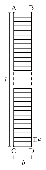
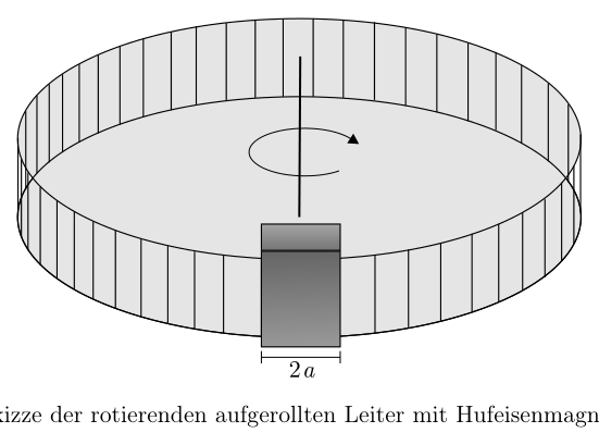
Problem 1 Eddy-current braking (19 points) Eddy currents induced by magnetic fields can be used to brake mechanical systems and are applied, for example, in modern trains as braking systems. In this problem you are to investigate a simple model system for braking a mechanical system by means of eddy currents. The ladder shown alongside, of total length l = 1,00 m, consists of thin copper wires with a diameter of d = 0,10 mm. The individual rungs have a length of b = 2,0 cm and are spaced a = 5,0 mm apart. a) Determine the electrical resistance of the ladder between points A and B. (5 points) The ladder is now rolled up into a ring such that points A and C as well as points B and D are connected to each other. The ring is fastened on the rim of a cut-off, thin-walled plastic bottle (cf. Fig. 1). The circular base of the bottle has a mass of 80 g, the wall on which the ring is fastened a mass of 20 g. The mass distribution in base and wall is homogeneous. The ring with the bottle can rotate freely about the symmetry axis drawn. A horseshoe magnet is now brought up to the ring, which, in a small section of the ring of width 2 a, produces a homogeneous magnetic field of magnetic flux density B = 0,60 T. Outside this small region the magnetic field is to be neglected. Figure 1: Sketch of the rotating rolled-up ladder with horseshoe magnet (in dark gray). b) Determine the torque acting on the rotating ring as a function of the parameters that appear, when the ring initially rotates about the axis with an angular frequency . (8 points) c) Compute how long it takes until the angular frequency of the ring has fallen to half its original value. (6 points) You may use the following values: Specific conductivity of copper = 58,0 106 Density of copper = 8920 kg 43. IPhO 2012 - Aufgaben der 2. Runde 3 / 8
 Ladder with points A B C D
 Rotating ring with horseshoe magnet
Topic: Electromagnetic Induction, Rotational Dynamics, Circuits Metodi: Faraday’s Law of Induction, Torque & Angular Momentum Analysis, Equivalent Circuit Reduction Competenze: Mathematical Modeling, Physical Reasoning, Diagrammatic Reasoning Objects: Coil, Wire, Magnet Fonte: Testo (PDF) — p.2
Problema 1 Braking a corrente eddy 19 punti) Eddy currents induciuti da campi magnetici possono essere utilizzati per frenare sistemi meccanici e sono applicati, per esempio, in moderna tecnologia.
- I sistemi di frenatura. In questo problema si deve indagare un sistema modello semplice per la frenata di un sistema meccanico Eddy currents. La scala mostrata al fianco, di totale lunghezza l = 1,00 m, è costituita da: di fibre di rame di colore inferiore o uguale a 0,10 mm. Il individui hanno una lunghezza di b = 2,0 cm e sono spaced a = 5,0 mm separati. a) Determina la resistenza elettrica della scala I punti A e B. 5 punti) La scala è ora rotolata in un anello come che punti A e C, nonché punti B e D sono collegati tra loro. Il ring è fissato sul bordo di un flacone di plastica a sottile parete (cf. Fig. 1). La base circolare della bottiglia ha un peso di 80 g, il muro su cui l’anello è fissato con una massa di 20 g. Il La distribuzione di massa in base e muro è omogenea. L’anello con la bottiglia può girare liberamente circa l’asse di simmetria disegnato. Un magnete da cavallo è ora portati fino al ring, che, in una piccola sezione del ring di larghezza 2 a, produce un campo magnetico omogeneo di densità di flusso magnetico B = 0,60 T. Outside this small Regione che il campo magnetico deve essere trascurato. Figura 1: Sketch of the rotating rolled-up ladder with horseshoe magnet (in dark gray). b) Determinare la torque che agisce sul ring rotante come funzione del parametri che appaiono quando l’anello inizia a rotare intorno all’asse con una frequenza angolare . (8 punti) c) Calcolare quanto tempo ci vorrà fino a quando la frequenza angolare del ring ha diminuito a metà del suo valore originale. (6 punti) Si possono utilizzare i seguenti valori: Specific conductivity of copper = 58,0 106 Densità di rame = 8920 kg
- IMP 2012 - Tasche del 2. Rondo 3 / 8
Ladder with points A B C D
Rotating ring with horseshoe magnet
Topic: Electromagnetic Induction, Rotational Dynamics, Circuits Metodi: Faraday’s Law of Induction, Torque & Angular Momentum Analysis, Equivalent Circuit Reduction Competenze: Mathematical Modeling, Physical Reasoning, Diagrammatic Reasoning Objects: Coil, Wire, Magnet Fonte: Testo (PDF) — p.2
Problem 1 is Eddy current braking The Commission’s proposal for a directive on the protection of workers Eddy currents induced by magnetic fields can be used to brake mechanical systems and are applied, for example, in modern trains as braking systems. In this problem you are to investigate a simple model system for braking a mechanical system by means of I’m not going to be able to get you to the next level. The ladder shown alongside, of total length l = 1,00 m, consists of of thin copper wires with a diameter of d = 0,10 mm. The individual rungs have a length of b = 2.0 cm and are spaced a = 5.0 mm apart. (a) Determine the electrical resistance of the ladder between points A and B. (five points) The ladder is now rolled up into a ring such that points A and C as well as points B and D are connected to each other. The ring is fastened on the rim of a cut-off, thin-walled plastic bottle (cf. Fig. 1). The circular base of the bottle has a mass of 80 g, The wall on which the ring is fastened a mass of 20 g. The Mass distribution in base and wall is homogeneous. The ring with the bottle can rotate freely about the symmetry axis drawn. A horseshoe magnet is now brought up to the ring, which, in a small section of the ring of width 2 a, produces a The magnetic field of the magnetic flux density B = 0,60 T. Outside this small region the magnetic field is to be neglected. Figure 1: Sketch of the rotating rolled-up ladder with horseshoe magnet (in dark gray). (b) Determine the torque acting on the rotating ring as a function of the parameters that appear when the ring initially rotates about the axis with an angular frequency . (80 points) (c) Calculate how long it takes until the angular frequency of the ring has fallen to half its original value. (seventh and sixth points) You may use the following values: Specific conductivity of copper = 58,0 106 Density of copper = 8920 kg 43. The Commission will also be able to take into account the specificities of the new rules. Round 3 / 8
Ladder with points A B C D
Rotating ring with horseshoe magnet
Topic: Electromagnetic Induction, Rotational Dynamics, Circuits Metodi: Faraday’s Law of Induction, Torque & Angular Momentum Analysis, Equivalent Circuit Reduction Competenze: Mathematical Modeling, Physical Reasoning, Diagrammatic Reasoning Objects: Coil, Wire, Magnet Fonte: Testo (PDF) — p.2
Problem 2 Fermat’s principle (19 points) (Idea: Manuel Bärenz) Fermat’s principle, named after Pierre de Fermat, forms the basis of the laws of reflection and refraction in ray optics and states, in simplified form, that light rays always propagate between two points along the paths on which they cover the distance between the points in the shortest time1. In this problem you are to investigate some consequences of this principle. a) Using Fermat’s principle, derive the well-known law of reflection angle of incidence = angle of reflection for the reflection of a light ray at a plane surface. (2 points) b) Likewise, using Fermat’s principle, derive Snell’s law of refraction for the transition from a medium n1 to a medium with refractive index n2. (3 points) For investigating the focusing of light rays by mirrors or lenses, Fermat’s principle is also very helpful. Light rays that emanate from a point light source and are focused at a point therefore have the same travel time along all paths between these two points. For the following problems, unless otherwise stated, assume that the light propagates in air. c) State what shape a mirror must have in order to focus the light of a point source completely at a point. In this part you do not need to give a mathematical function for the mirror surface. (3 points) d) Determine how a mirror must be shaped in order to focus the light of a very distant, small light source at a point. Assume for this that the focal point is located at the coordinate origin and the light source along one of the coordinate axes. Give the shape of the mirror surface as a function. (4 points) e) Let a lens with refractive index n be plane on one side and have on the other side a profile y(x) with y(0) =: y0, where the consideration here is restricted to the x-y plane. Let the plane side of the lens be parallel to the x-axis. Determine how the lens must be shaped, i.e. how the function y(x) must look, in order to focus light that falls parallel to the y-axis from negative infinity onto the plane side at the point (0, d) with d behind the lens. Finally consider the case d = y0 and state what physical meaning the slope of the function y(x) has in this case. (7 points) 1The exact formulation states that the light path is a stationary point of the time functional. 43. IPhO 2012 - Aufgaben der 2. Runde 4 / 8
Topic: Geometric Optics Metodi: Ray Tracing, Snell’s Law, Calculus-Integration Competenze: Mathematical Modeling, Physical Reasoning, Diagrammatic Reasoning Objects: Mirror, Lens Fonte: Testo (PDF) — p.3
Problema 2 Il principio di Fermat 19 punti) (idea: Manuel Bärenz) Il principio di Fermat, intitolato a Pierre de Fermat, costituisce la base delle leggi della riflessione e della Refrazione in radioptica e stati, in forma semplificata, che i raggi di luce Propagano sempre tra due punti lungo i percorsi su cui coprono la distanza tra I punti nel più breve tempo1. In questo problema si devono indagare alcune conseguenze di questo principio. a) Usando il principio di Fermat, derivare la ben nota legge di riflessione angolo di incidenza = angolo di riflessione per il riflesso di un raggio di luce a una superficie piana. (2 punti) b) Come, usando il principio di Fermat, derivare la legge di refrazione di Snell per la transizione da un mezzo n1 a un mezzo con indice refraettivo n2. (3 punti) Per indagare la messa a fuoco dei raggi luminosi da specchi o lenti, il principio di Fermat è anche molto utile. Raggi luminosi che emettono da una fonte luminosa di punto e sono focalizzati su un punto quindi hanno lo stesso tempo di viaggio lungo tutti i percorsi tra questi due punti. Per i seguenti problemi, a meno che non sia diversamente indicato, Supponiamo che la luce si diffonda nell’aria. c) State what shape a mirror must have in order to focus the light of a point source Completamente a un certo punto. In questa parte non è necessario dare una funzione matematica per la superficie dello specchio. (3 punti) d) Determinare come un specchio deve essere formato per focalizzare la luce di una fonte di luce molto lontana e piccola ad un punto. Supponiamo che il punto focale sia situato all’origine delle coordinate e alla fonte luminosa lungo uno degli assi delle coordinate. Date la forma della superficie dello specchio come funzione. (4 punti) e) Lasciate che un lente con indice refraettivo n sia piano su un lato e abbiate l’altro lato a Profile y(x) with y(0) =: y0, where the consideration here is restricted to the x-y plane. Lasciate che il lato piano della lente sia parallelo all’asse x. Determina come la lente deve essere modellata, cioè come la funzione y(x) deve guardare, per concentrare la luce che cade parallela all’asse y dall’infinito negativo sul lato piano a the point (0, d) with d behind the lens. Finalmente considerate il caso d = y0 e state what physical meaning la slope della funzione y(x) ha in questo caso. 7 punti) 1La formulazione esatta afferma che il percorso della luce è un punto stazionario del tempo funzionale. 43. IMP 2012 - Tasche del 2. Rondo 4 / 8
Topic: Geometric Optics Metodi: Ray Tracing, Snell’s Law, Calculus-Integration Competenze: Mathematical Modeling, Physical Reasoning, Diagrammatic Reasoning Objects: Mirror, Lens Fonte: Testo (PDF) — p.3
Problem 2 Fermat’s principle The Commission’s proposal for a directive on the protection of workers (Ideas: Manuel Bärenz) Fermat’s principle, named after Pierre de Fermat, forms the basis of the laws of reflection and refraction in ray optics and states, in simplified form, that light rays They always propagate between two points along the paths on which they cover the distance between The points in the shortest time1. In this problem you are to investigate some consequences of this principle. (a) Using Fermat’s principle, derive the well-known law of reflection angle of incidence = angle of reflection for the reflection of a light ray at a plane surface. (two points) (b) Likewise, using Fermat’s principle, derive Snell’s law of refraction for the transition from a medium n1 to a medium with refractive index n2. (three points) For investigating the focusing of light rays by mirrors or lenses, Fermat’s principle is also very helpful. Light rays that emanate from a point light source And are focused at a point so have the same travel time along all paths between these two points. For the following problems, unless otherwise stated, Assume that the light propagates in air. (c) State what shape a mirror must have in order to focus the light of a point source completely at a point. In this part you don’t need to give a mathematical function for the mirror surface. (three points) (d) Determine how a mirror must be shaped in order to focus the light of a very distant, small light source at a point. Assume for this that the focal point is located at the coordinate origin and the light source along one of the coordinate axes. Give the shape of the mirror surface as a function. (four points) (e) Let a lens with refractive index n be plane on one side and have on the other side a profile y(x) with y(0) =: y0, where the consideration here is restricted to the x-y plane. Let the plane side of the lens be parallel to the x-axis. Determine how the lens must be shaped, i.e. how the function y(x) must look, In order to focus light that falls parallel to the y-axis from negative infinity onto the plane side at the point (0, d) with d behind the lens. Finally consider the case d = y0 and state what physical meaning the slope of the function y(x) has in this case. (seventh and final points) 1The exact formulation states that the light path is a stationary point of the time functional. 43. The Commission will also be able to take into account the various aspects of the project. Round 4 / 8
Topic: Geometric Optics Metodi: Ray Tracing, Snell’s Law, Calculus-Integration Competenze: Mathematical Modeling, Physical Reasoning, Diagrammatic Reasoning Objects: Mirror, Lens Fonte: Testo (PDF) — p.3
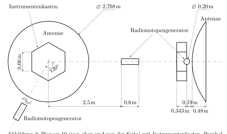
Problem 3 Pioneer anomaly (31 points) (Idea: Bastian Hacker) The space probe Pioneer 10 was launched in 1972 to explore the outer Solar System and was to be the first spacecraft to leave the Solar System definitively. After the probe had, in 1980, moved far enough from the Sun at 20 AU to be able to predict the influence of various forces accurately enough, an inexplicable, tiny component in its acceleration was discovered. This so-called Pioneer anomaly has been much investigated since then and has given rise to numerous speculations about possible modifications of the laws of nature. In this problem you are to investigate some possible explanations of this Pioneer anomaly using simple models. For this you may start from a simplified construction of the Pioneer 10 probe, consisting mainly of a hexagonal box on which the scientific instruments are mounted, as well as a flat parabolic antenna of diameter d = 2,77 m, which is always directed toward Earth (cf. Fig. 2). For stabilization, the probe was set into rotation about the antenna axis at a rate of about 4,8 revolutions per minute. After the last orbit corrections, the total mass of the probe is m = 241 kg. a) Pioneer 10 left the gravitational field of the Earth with a velocity of v0 = 9,4 km relative to the Earth and tangential to its orbit. On arrival at Jupiter with orbital radius 5,2 AU, it performed a swing-by maneuver in order to finally leave the Solar System. Assume that the maneuver was carried out such that the probe can leave the Solar System with the highest possible velocity. In addition, the time during which Pioneer 10 interacts gravitationally with Jupiter can be assumed to be short compared with the rest of the flight time. Give the radial velocity vr(r) and in particular the limiting velocity ) of the probe after this maneuver as a function of the distance r to the Sun. Treat all processes within the ecliptic and assume the planetary orbits to be circular. (8 points) b) The strongest force on the probe after gravity is caused by the radiation pressure due to solar radiation. The parabolic antenna, which at larger distances points roughly toward the Sun, absorbs 20% of the sunlight and reflects the rest back toward the Sun. Determine approximately the acceleration that thereby results for the probe at a distance r AU from the Sun. State how large the contribution was in the year 1990 for r = 50 AU. (4 points) c) In addition, the Sun emits the solar wind, a stream of hydrogen plasma that reaches out to a distance of at least 80 AU from the Sun. Near Earth, the proton density of the solar wind is n0 106 . The particle velocity of the solar wind is v km in the radial direction. Estimate the influence of the solar wind on the acceleration of the probe at a distance of 50 AU from the Sun as well as at larger distances r. (3 points) d) The large parabolic antenna continuously transmits a focused radio beam with an output power of 8 W toward Earth. Determine its influence too on the acceleration of the probe. (2 points) 43rd IPhO 2012 - Problems of the 2nd Round 5 / 8 e) The Pioneer trajectory could be computed with high precision, taking into account the gravitational force of the Sun, planets and other celestial bodies according to the formulas of general relativity. The radiation pressure can also be modeled accurately to the order of magnitude of the solar wind. To measure the actual probe position, the travel time of a radio signal between Earth and probe was used. The high-precision velocity determination was carried out via the Doppler shift of the phase-accurately returned radio signals. The carrier frequency of the signal2 was 2,292 GHz. Determine the expected frequency shift of the carrier frequency at a probe distance of r = 50 AU, neglecting the accelerations determined in parts b)-d) and with the simplifying assumption of an Earth at rest relative to the Sun. If you have not solved part a), you may use the substitute value vr km for the radial velocity of the probe. Even after including all known effects that lead to an acceleration of the probe, a constant additional drift of the frequency shift of d /d t = Hz remained. Determine how large the additional acceleration of the probe must be in order to cause this effect. (4 points) f) As a possible cause of this acceleration, the thermal radiation of the onboard power supply was considered. The effect of an anisotropic radiation had namely been underestimated in earlier analyses. Figure 2 shows the probe schematically. Figure 2: Pioneer 10 (from above and from the side) with instrument box, parabolic antenna (toward Earth) and radioisotope generators (small cylinders). The power supply of the probe is provided by radioisotope generators that are powered with plutonium (half-life: 88 a) and at launch provided a thermal power P0 = 2580 W. Thermocouples generate electricity from this with an efficiency of 3,9%. The radioisotope generators, shown as 2In fact this carrier frequency was emitted by the probe, while the frequency of the signal sent from Earth was still multiplied by a fixed factor. This, however, plays no role for the consideration and is therefore to be disregarded. 43rd IPhO 2012 - Problems of the 2nd Round 6 / 8 small cylinders, are spatially separated from the main body of the probe and radiate their unused heat through small fins symmetric to the direction of flight in such a way that the probe is hardly struck by it. In the hexagonal box the entire electrical power is consumed, with the exception of the power radiated by the antenna. The top side of the box visible in the left sketch conducts heat about four times as well as the rest of the box. Estimate the additional acceleration of the probe in the year 1990 due to thermal radiation. This is not about an exact calculation but about approximating the result sensibly. For this, strongly simplifying assumptions may be made, which must, however, be plausible and should be justified as well as possible. You may assume that the warm surfaces radiate with a Lambertian characteristic depending on the angle to the surface normal, i.e. that the radiated power emitted per solid-angle fraction by a surface element is proportional to ). Assume in addition that of the thermal radiation striking the probe, 80% is reflected and the rest absorbed. Assess whether the Pioneer anomaly can be explained by means of thermal radiation. Give both arguments for and against it. (10 points) The following values may be helpful for working on the problem: Radius of the Earth’s orbit (Astronomical Unit) 1 AU = 149,6 106 km Solar mass MS = 1,99 1030 kg Solar constant (solar irradiance near Earth) E0 = 1367 W Proton mass mp = 1,6726 kg
 Pioneer 10 probe seen from above and from the side
Topic: Gravitation, Special Relativity, Astrophysics Metodi: Conservation of Energy, Newton’s Law of Gravitation, Approximation & Series Expansion Competenze: Estimation & Approximation, Mathematical Modeling, Physical Reasoning Objects: Satellite, Star, Planet Fonte: Testo (PDF) — p.4
Problema 3 Anomalia di pioniere (31 punti) (idea: Bastian Hacker) La sonda spaziale Pioneer 10 è stata lanciata nel 1972 per esplorare il sistema solare esterno e che sarebbe stata la prima sonda spaziale a lasciare definitivamente il sistema solare. Dopo la prova, nel 1980, si è spostato abbastanza lontano dal Sole a 20 UA per essere in grado di prevedere l’influenza di varie forze Accuratamente abbastanza, un componente inesplicabile, minuscolo nella sua accelerazione è stato scoperto. Questa cosiddetta anomalia pionieristica è stata molto indagata da allora e Ha dato luogo a numerose speculazioni circa possibili modifiche delle leggi della natura. In questo problema si sono per indagare alcune possibili spiegazioni di questo anomalia pioniere utilizzando semplice modello. Per questo potete partire da una costruzione semplificata del test Pioneer 10, consistente principalmente di una scatola hexagonale su cui sono montati gli strumenti scientifici, nonché una antenna parabolica piatta di diametro d = 2,77 m, che è sempre diretta verso la Terra (cf. Fig. 2). Per la stabilizzazione, la sonda è stata messa in rotazione circa l’asse dell’antenna a un ritmo di circa 4,8 rivoluzioni al minuto. Dopo le ultime correzioni orbitali, la massa totale della prova è m = 241 kg. a) Pioneer 10 ha lasciato il campo gravitazionale della Terra con una velocità di v0 = 9,4 km relativa alla Terra e tangenziale alla sua orbita. All’arrivo a Giove con Radius orbitale di 5,2 AU, ha eseguito una manovra di swing-by per finalmente lasciare il sistema solare. Supponiamo che la manovra è stata effettuata in modo che la sonda può lasciare il Sistema solare con la massima velocità possibile. Inoltre, il tempo Durante il quale Pioneer 10 interagisce gravitazionalmente con Giove si può presumere che sia breve rispetto al resto del pianeta.
- Tempo di volo. Give the radial velocity vr(r) and in particular the limiting velocity ) della sonda dopo questa manovra in funzione della distanza r dal Sole. Trattamento Tutti i processi all’interno dell’eclittica e assumono le orbite planetarie di essere circolari. (8 punti) b) La forza più forte sulla sonda dopo la gravità è causata dalla pressione di radiazione dovuta a
- Il sole. L’antenna parabolica, che a più grandi distanze punti verso il sole, assorbe il 20% della luce solare e riflette il resto indietro verso il sole. Determine approximately the acceleration that thereby results for the probe at a distance r AU from the Sun. State how large the contribution was in the year 1990 for r = 50 AU. (4 punti) c) Inoltre, il Sole emette il vento solare, un flusso di plasma idrogeno che raggiunge a una distanza di almeno 80 UA dal Sole. Near Earth, the proton density of the solar wind is n0 106 . La velocità delle particelle del vento solare è v km in the radial direction. Estimare l’influenza del vento solare sull’accelerazione della sonda a una distanza di 50 AU dal Sole e a distanze più grandi r. (3 punti) d) La grande antenna parabolica trasmette continuamente un fascio radio focalizzato con un Potenza di uscita di 8 W verso la Terra. Determina la sua influenza anche sull’accelerazione della prova. (2 punti) 43° IPhO 2012 - Problemi del 2° round 5 / 8 e) La traiettoria pionieristica potrebbe essere calcolata con alta precisione, tenendo conto della forza gravitazionale del Sole, dei pianeti e di altri corpi celesti secondo le formule della relatività generale. La pressione di radiazione può anche essere modellata accuratamente all’ordine di magnitudo del vento solare. Per misurare la posizione attuale della sonda, il tempo di viaggio di un segnale radio tra Terra e prova cosa usato. La determinazione di velocità ad alta precisione che è stata effettuata attraverso il Doppler shift della fase-accuratamente restituito segnali radio. La frequenza di trasporto del Signal2 che è 2.292 GHz. Determine il cambiamento di frequenza atteso della frequenza del vettore a la distanza di prova di r = 50 AU, trascurando le accelerazioni determinate nelle parti b) -d) e con l’assunzione semplificante di un’Earth at rest relative al Sole. Se non hai risolto parte a), puoi usare il valore sostitutivo vr km per la velocità radiale della prova. Anche dopo aver incluso tutti gli effetti noti che portano ad un’accelerazione della sonda, a constant additional drift of the frequency shift of d /d t = Hz remained. Determina quanto maggiore deve essere l’accelerazione aggiuntiva della sonda per causare questo effetto. (4 punti) f) Come causa possibile di questa accelerazione, la radiazione termica della alimentazione onboard è stata considerata. L’effetto di una radiazione anisotrope ha avuto Le ricerche hanno dimostrato che il tasso di crescita è stato sottovalutato in analisi precedenti. La figura 2 mostra la prova schematicamente. Figura 2: Pioneer 10 (da sopra e dal lato) con strumento box, antenna parabolica (verso la Terra) e generatori radioisotopi (piccoli cilindri). La potenza della sonda è fornita da generatori radioisotopi che sono alimentati con plutonio (half-life: 88 a) e a lancio fornito una potenza termica P0 = 2580 W. I termoparti generano elettricità da questo con un’efficienza del 3,9%. I generatori di radioisotopi, mostrati come 2In fact, questa frequenza portatrice è stata emessa dalla sonda, mentre la frequenza del segnale inviato dalla Terra che moltiplicato per un fattore fisso. Questo, tuttavia, non svolge alcun ruolo per la considerazione e deve quindi essere ignorato. 43° IPhO 2012 - Problemi del 2° round 6 / 8 piccoli cilindri, spazialmente separati dal corpo principale di questa sonda e di irradiare il loro calore non usato attraverso piccole pinne simmetrici alla Direzione di volo in modo tale che la sonda è difficilmente colpita da esso. In questa casella esagonale l’intera potenza elettrica è consumata, con l’eccezione della potenza irradiata dalla
- Antenna. Il lato superiore della scatola visibile nello schizzo sinistro Conduce calore circa quattro volte così come il resto della scatola. Estimare l’accelerazione aggiuntiva della sonda nell’anno 1990 a causa delle radiazioni termiche. Questo non è un calcolo preciso, ma circa approximating the result sensibly. Per questo, possono essere fatte ipotesi fortemente semplificanti, che devono, tuttavia, essere plausibili e dovrebbero essere giustificate come possibile. Potete supporre che le superfici calde irradiano con una caratteristica lambertiana a seconda dell’angolo alla superficie normale, cioè che la potenza irradiata emessa per frazione a solido angolo da un elemento di superficie è proporzionale a ). Supponiamo che, in aggiunta, l’80% della radiazione termica che colpisce la sonda sia riflessa e il resto assorbita. Assess se l’anomalia pionieristica può essere spiegata con mezzi di radiazione termica. Date entrambi gli argomenti a favore e contro. 10 punti I seguenti valori possono essere utili per lavorare sul problema: Radius of the Earth’s orbit (unità astronomica) 1 AU = 149,6 106 km Massa solare MS = 1,99 1030 kg Costante solare (irradiazione solare vicino alla Terra) E0 = 1367 W Massa protonica mp = 1,6726 kg
Pioneer 10 probe seen from above and from the side
Topic: Gravitation, Special Relativity, Astrophysics Metodi: Conservation of Energy, Newton’s Law of Gravitation, Approximation & Series Expansion Competenze: Estimation & Approximation, Mathematical Modeling, Physical Reasoning Objects: Satellite, Star, Planet Fonte: Testo (PDF) — p.4
Problem 3 Pioneer anomaly (Twenty-one points) (Idea: Bastian Hacker) The space probe Pioneer 10 was launched in 1972 to explore the outer solar system and the Earth. It’s the first spacecraft to leave the solar system. After the probe had, In 1980, moved far enough from the Sun at 20 AU to be able to predict the influence of various forces Accurately enough, an inexplicable, tiny component in its acceleration was discovered. This so-called pioneer anomaly has been much investigated since then and has given rise to numerous speculations about possible modifications of the laws of nature. In this problem you are to investigate some possible explanations of this pioneer anomaly using simple models. For this you may start from a simplified construction of the Pioneer 10 probe, consisting mainly of of a hexagonal box on which the scientific instruments are mounted, as well as a flat parabolic antenna of diameter d = 2.77 m, which is always directed towards Earth (cf. Fig. 2). For stabilization, the probe was set into rotation about the antenna axis At a rate of about 4.8 revolutions per minute. After the last orbital corrections, the total mass of the probe is m = 241 kg. a) Pioneer 10 left the gravitational field of the Earth with a velocity of v0 = 9.4 km relative to the Earth and tangential to its orbit. On arrival at Jupiter with orbital radius of 5.2 AU, it performed a swing-by maneuver in order to finally leave the solar system. Assume that the maneuver was carried out such that the probe can leave the Solar system with the highest possible velocity. In addition, the time During which Pioneer 10 interacts gravitationally with Jupiter can be assumed to be short compared with the rest of the Flight time. Give the radial velocity vr(r) and in particular the limiting velocity ) of the probe after this maneuver as a function of the distance r to the Sun. Treat All processes within the ecliptic and assume the planetary orbits to be circular. (80 points) (b) The strongest force on the probe after gravity is caused by the radiation pressure due to The solar radiation. The parabolic antenna, which at larger distances points roughly It absorbs 20% of the sunlight and reflects the rest back. towards the sun. Determine approximately the acceleration that thereby results for the probe at a distance r AU from the Sun. State how large the contribution was in the year 1990 for r = 50 AU. (four points) (c) In addition, the Sun emits the solar wind, a stream of hydrogen plasma that reaches the out to a distance of at least 80 AU from the Sun. Near Earth, the proton density of the solar wind is n0 106 . The particle velocity of the solar wind is v km in the radial direction. Estimate the influence of the solar wind on the acceleration of the probe at a distance of 50 AU from the Sun as well as at greater distances r. (three points) (d) The large parabolic antenna continuously transmits a focused radio beam with an output power of 8 W toward Earth. Determine its influence too on the acceleration of the probe. (two points) 43rd IPhO 2012 - Problems of the 2nd Round 5 / 8 (e) The pioneer trajectory could be computed with high precision, taking into account the gravitational force of the Sun, planets and other celestial bodies according to the formulas of general relativity. The radiation pressure can also be modeled accurately to the order of magnitude of the solar wind. To measure the actual probe position, the travel time of a radio signal between Earth and probe what used. The high-precision velocity determination was carried out via the Doppler shift of the phase-accurately returned radio signals. The carrier frequency of the signal2 is 2,292 GHz. Determine the expected frequency shift of the carrier frequency at a probe distance of r = 50 AU, neglecting the accelerations determined in parts b) to d) and with the simplifying assumption of an Earth at rest relative to the Sun. If you have not solved part a), you may use the substitute value vr km for the radial velocity of the probe. Even after including all known effects that lead to an acceleration of the probe, a constant additional drift of the frequency shift of d /d t = The frequency of the measurement is set at Hz remained. Determine how large the additional acceleration of the probe must be in order to cause this effect. (four points) (f) As a possible cause of this acceleration, the thermal radiation of the onboard power supply was considered. The effect of an anisotropic radiation had namely The results of the study were not as accurate as previous analyses. Figure 2 shows the probe schematically. Figure 2: Pioneer 10 (from above and from the side) with instrument box, parabolic antenna (towards Earth) and radioisotope generators (small cylinders). The power supply of the probe is provided by radioisotope generators that are powered with plutonium (half-life: 88 a) and at launch provided a thermal power P0 = 2580 W. Thermocouples generate electricity from this with an efficiency of 3.9%. The radioisotope generators, shown as 2In fact this carrier frequency was emitted by the probe, while the frequency of the signal sent from Earth Which is still multiplied by a fixed factor. This, however, plays no role for the consideration and is therefore to be disregarded. 43rd IPhO 2012 - Problems of the 2nd Round 6 / 8 Small cylinders, are spacially separated from the main body of the probe and radiate their unused heat through small fins symmetrical to the direction of flight in such a way that the probe is hardly hit by it. In the hexagonal box the entire electrical power is consumed, with the exception of the power radiated by the The antenna. The top side of the box visible in the left sketch conducts heat about four times as well as the rest of the box. Estimate the additional acceleration of the probe in the year 1990 due to thermal radiation. This is not about an exact calculation but about Approximating the result sensibly. For this, strongly simplifying assumptions may be made, which must, however, be plausible and should be justified as well as possible. You may assume that the warm surfaces radiate with a Lambertian characteristic depending on the angle to the surface normal, i.e. that the radiated power emitted per solid-angle fraction by a surface element is proportional to ). Assume in addition that of the thermal radiation striking the probe, 80% is reflected and the rest absorbed. Assess whether the pioneer anomaly can be explained by means of thermal radiation. Give both arguments for and against it. (Figure 1) The following values may be helpful for working on the problem: Radius of the Earth’s orbit (astronomical unit) 1 AU = 149,6 106 km Solar mass MS = 1,99 1030 kg Solar constant (solar irradiance near Earth) E0 = 1367 W Proton mass mp = 1,6726 kg
Pioneer 10 probe seen from above and from the side
Topic: Gravitation, Special Relativity, Astrophysics Metodi: Conservation of Energy, Newton’s Law of Gravitation, Approximation & Series Expansion Competenze: Estimation & Approximation, Mathematical Modeling, Physical Reasoning Objects: Satellite, Star, Planet Fonte: Testo (PDF) — p.4
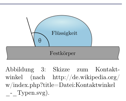
Problem 4 Experimental problem - Physics of a trickle (8 + 18 + 5 points) (Idea: Georg Schröter) In this experimental problem you are to investigate the surface tension and the viscosity of water. For the experiments you may use all common household items and can, if needed, additionally borrow accurate measuring cups, pipettes or an accurate scale, e.g. from school. In both parts you need a smooth plane. Suitable for this is, e.g., a flat board coated with the wax of a tealight. Describe your theoretical considerations, the experimental setups, the experimental procedure and the analysis in such a way that they are easily comprehensible. The results obtained will be comparatively inaccurate and should each contain an error estimate. 4.1 Surface tension of water The surface tension of a liquid is defined as the ratio of the energy that is required to enlarge the surface by , to the surface enlargement, i.e. = . Likewise, for every interface between a liquid and another material (solid, liquid or gas) there exists an interfacial tension that is defined in the same way and depends on the adjoining materials; it can be either positive or negative. The surface tension is then the interfacial tension to vacuum (or to a thin gas). 43rd IPhO 2012 - Problems of the 2nd Round 7 / 8 In weightlessness, liquids form spherical drops due to surface tension. If a liquid is on a surface under the influence of gravity, surface tension and interfacial tension cause the liquid to be pushed somewhat “upward” and thus to occupy only a limited area; it forms a puddle. In addition, the ratio of the two tensions3 determines the size of the angle that liquid and substrate enclose with each other: cos = . Solid Liquid Θ Figure 3: Sketch of the contact angle (after http://de.wikipedia.org/ w/index.php?title=Datei:Kontaktwinkel _-_Typen.svg). The total mechanical energy of the puddle now consists of the potential energy and the energy of the surface and interface. In the static case the puddle takes on a shape that minimizes the total energy. In the following you are to investigate drops or small puddles with fixed volume on a smooth plane within the framework of simple model assumptions: a) Assume that the shape of the puddle corresponds to a flat cylinder with height h and radius r. The influence of the contact angle on the geometric shape is thus to be neglected. Use the fact that the shape of the puddle minimizes the mechanical energy at fixed liquid volume V and derive an expression for the surface tension as a function of experimentally measurable quantities. (3 points) b) Determine experimentally, as accurately as possible, the surface tension of tap water. (5 points) 4.2 Determination of the viscosity of water When a Newtonian liquid flows down an inclined plane without turbulence (laminar), the individual liquid layers slide over one another with different velocities. Directly at the interface to the substrate, the velocity of the liquid relative to the inclined plane is equal to 0. With increasing distance x from the plane the velocity increases, so that a velocity profile v(x) develops. Liquid layers lying on top of each other exert on each other a frictional force proportional to the velocity gradient: FR = A dv dx , where denotes the (dynamic) viscosity of the liquid and A is the contact area of the layers. The forces that arise are much smaller than the direct frictional forces between two solids, so that objects can practically glide on a liquid film. Figure 4: Water trickle. If the plane is not inclined too strongly, after a short time a stationary flow behavior is established and the liquid is not accelerated further downward. In this process, surface and interfacial tension draw the liquid together into a narrow trickle. 3Strictly speaking, the interfacial tension here is the difference of the interfacial tension between the surface and air and the interfacial tension between the surface and the liquid. 43rd IPhO 2012 - Problems of the 2nd Round 8 / 8 c) Similarly to the previous part, the trickle also takes on a shape that, at fixed cross-sectional area A, minimizes the energy (here, however, per length). As a simplified model, assume that the shape of the trickle corresponds to a cuboid of width b and thickness h. Show that for the thickness of the trickle (or of the cuboid), as a function of the width b and the small inclination angle of the plane, the following holds: h = 2 g b cos r (1 ) cos b2 g 2
- 1 ! . Neglect edge effects that arise. (2 points) d) Now determine the velocity profile v(x) of the trickle that is established at small inclination angles . Note that the velocity at the substrate must be equal to zero (v(0) = 0) and use the fact that the velocity profile at the top of the liquid satisfies the condition dv/dx(h) = 0. (3 points) e) Show with this that for the liquid volume flowing through a fixed cross-section per time , the following holds = sin g b h3 3 . (2 points) f) By investigating a water trickle, determine experimentally the viscosity of water. (8 points) g) Compare your result with the actual viscosity of water and discuss causes of possible deviations. (3 points) 4.3 Comparison experiment for the determination of viscosity The dynamic viscosity of water can also be determined in other ways. A method that is experimentally simple to carry out is determination via the flow resistance through a thin tube using the law of Hagen-Poiseuille. h) Determine the viscosity of water by measuring the flow resistance through a thin tube, and compare the result with the result from the previous part. (5 points) For the experimental problem use the following values: Gravitational acceleration on the Earth g = 9,81 m Density of water = 1000 kg Good luck!
 Contact angle of a drop on a surface
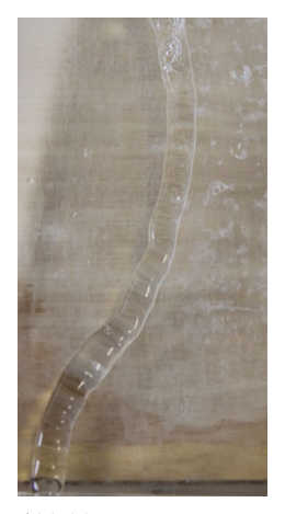 Photo of a water trickle on an inclined plane
Topic: Fluid Mechanics, Newtonian Mechanics Metodi: Hydrostatic Equilibrium, Differential Equations, Energy Conservation Method Competenze: Experimental Data Analysis, Error Propagation, Measurement & Instrumentation Objects: Droplet, Inclined Plane Fonte: Testo (PDF) — p.6
Problema 4 Problema sperimentale - Fisica di un trucco (8 + 18 + 5 punti) (idea: Georg Schröter) In questo problema sperimentale si deve indagare sulla tensione superficiale e sulla viscosità dell’acqua. Per gli esperimenti si possono utilizzare tutti gli articoli di uso domestico e può, se necessaria, additionally borrow accurate measuring cups, pipettes or an accurate scale, e.g. - di scuola. In entrambi i casi, hai bisogno di un piano liscio. Adatta a questo è, ad esempio, un una tavola piatta rivestita della cera di un tealight. Descrivere le vostre considerazioni teoriche, le configurazioni sperimentali, la procedura sperimentale e l’analisi in modo che siano facilmente comprensibili. I risultati ottenuti saranno comparatively inaccurate and should each contain an error estimate. 4.1 Tensione di superficie dell’acqua La tensione di superficie di un liquido è definita come il rapporto di energia che è richiesto di allargare la superficie da , cioè = . Allo stesso modo, per ogni interfaccia tra un liquido e un altro materiale (solido, liquido o gas) esiste una tensione interfaciale che è definita nello stesso modo. e dipende dai materiali adiacenti; può essere positivo o negativo. La tensione di superficie è quindi la tensione interfaciale a vuoto (o a gas). 43° IPhO 2012 - Problemi del 2° round 7 / 8 In weightlessness, liquidi form spherical gocce a causa di tensione superficiale. Se un liquido è su una superficie sotto l’influenza di gravità, tensione di superficie e tensione interfaciale cause il liquido da spingere “upward” e In questo modo occuparsi solo di un’area limitata; esso forma
- Un po’ di acqua. Inoltre, il rapporto di due tensions3 determinano la dimensione dell’angolo che liquido e substrato si inseriscono tra loro: cos = . Solidità Liquidità Θ Figura 3: Sketch di angolo di contatto (dopo http://de.wikipedia.org/ l/index.php?title=File:angolo di contatto
L’energia meccanica totale del puddle now consiste nell’energia potenziale e l’energia di energia della superficie e dell’interfaccia. In static case il puddle assume una forma che minimizza l’energia totale. In the following you are to investigate drops or small puddles with fixed volume on a smooth plane within the framework of simple model assumptions: a) Supponiamo che la forma del puddle corrisponda a un cilindro piatto con altezza h e raggio r. L’influenza dell’angolo di contatto sulla forma geometrica deve quindi essere trascurata. Usare il fatto che la forma del pozzo minimizza l’energia meccanica a fissa volume liquido V and derive an expression for the surface tension come funzione di quantità misurabili sperimentalmente. (3 punti) b) Determine sperimentalmente, con la massima precisione possibile, la tensione di superficie dell’acqua di rubinetto. 5 punti) 4.2 Determinazione della viscosità dell’acqua Quando un liquido newtoniano scorre verso il basso in un piano inclinato senza turbolenza (laminar), gli singoli strati liquidi slide
- Si sono messe in una posizione che non è la stessa. Direttamente al Interfaccia al substrato, la velocità del liquido relativa al piano inclinato è pari a 0. Con crescente distanza x dal plane la velocità aumenta, così che un profilo di velocità v(x) si sviluppa. Liquid layers lying on top of each other esercitare su di loro una forza di frattura proporzionale al gradiente di velocità: FR = A dv dx , dove denota la viscosità (dinamica) del liquido e A è l’area di contatto dei strati. Le forze che si presentano sono molto più piccolo delle forze di frizione dirette tra due solidi, in modo che gli oggetti possono praticamente Gliede on a liquid film. Figura 4:
- Water trickle. Se il piano non è inclinato troppo fortemente, dopo un breve tempo si stabilisce un comportamento di flusso stazionario e il liquido non si accelera ulteriormente verso il basso. In questo processo, la superficie e Interfacial tension draw the liquid together into a narrow trickle. 3Strictly speaking, la tensione interfaciale qui è la differenza della tensione interfaciale tra la superficie e l’aria e la tensione interfaciale tra la superficie e il liquido. 43° IPhO 2012 - Problemi del 2° round 8 / 8 c) Simile alla parte precedente, il tricollo assume anche una forma che, a fissa area cross-sectional A, minimizza l’energia (qui, tuttavia, per lunghezza). Come modello semplificato, supponiamo che la forma del tricollo corrisponda a un cuboide di larghezza b and thickness h. Mostra che per lo spessore del cuboide, come funzione della larghezza b e il piccolo angolo di inclinamento del piano, il seguente: h = 2 g b cos r (1 ) cos b2 g 2
- 1 ! . Negli effetti che si verificano. (2 punti) d) Now determine the velocity profile v(x) of the trickle that is established at small inclination angles . Nota che la velocità al substrato deve essere uguale a zero (v(0) = 0) e utilizzare il fatto che il profilo di velocità al vertice del liquid satisfies the condition dv/dx(h) = 0. (3 punti) e) Show with this that for the liquid volume flowing through a fixed cross-section per time , the following holds = sin g b h3 3 . (2 punti) f) Investigando un’acqua che si scorre, determinare sperimentalmente la viscosità di acqua. (8 punti) g) Compare il tuo risultato con l’effettiva viscosità dell’acqua e discutere Cause of possible deviations. (3 punti) 4.3 Comparare l’esperimento per la determinazione della viscosità La viscosità dinamica dell’acqua può essere determinata anche in altri modi. Un metodo che è sperimentale semplice da portare a termine è la determinazione attraverso la resistenza di flusso attraverso un tubo sottile usando la legge di Hagen-Poiseuille. h) Determina la viscosità di acqua misurando la resistenza di flusso attraverso un thin tube, and compare the result with the result from the previous
- La parte. 5 punti) Per il problema sperimentale utilizzare i seguenti valori: Accelerazione gravitazionale sulla Terra g = 9,81 m Densità di acqua = 1000 kg
- Buona fortuna!
Contact angle of a drop on a surface
Foto di un water trickle on an inclined plane
Topic: Fluid Mechanics, Newtonian Mechanics Metodi: Hydrostatic Equilibrium, Differential Equations, Energy Conservation Method Competenze: Experimental Data Analysis, Error Propagation, Measurement & Instrumentation Objects: Droplet, Inclined Plane Fonte: Testo (PDF) — p.6
The problem is 4 The experimental problem - Physics of a trickle (eight + 18 + five points) (Ideas: Georg Schröter) In this experimental problem you are to investigate the surface tension and the viscosity of water. For the experiments you may use all common household items and can, if Other, including the use of a measuring cup, pipette or an accurate scale, e.g. From school. In both places you need a smooth plan. Suitable for this is, e.g., a flat board coated with the wax of a tealight. Describe your theoretical considerations, the experimental setups, the experimental procedure and the analysis in such a way that they are easily comprehensible. The results obtained will be The data should be comparatively inaccurate and should each contain an error estimate. 4.1 Surface tension of water The surface tension of a liquid is defined as the ratio of the energy that is required to enlarge the surface by , to the surface enlargement, i.e. = . Similarly, for every interface between a liquid and another material (solid, liquid or gas) there exists an interfacial tension that is defined in the same way and depends on the adjoining materials; it can be either positive or negative. The surface tension is then the interfacial tension to vacuum (or to a The following table shows the following: 43rd IPhO 2012 - Problems of the 2nd Round 7 / 8 In weightlessness, liquids form spherical drops due to surface tension. If a liquid is on a surface under the influence of Gravity, surface tension and interfacial tension cause The liquid to be pushed upwards and Thus to occupy only a limited area; it forms A puddle. In addition, the ratio of the two tensions3 determines the size of the angle that liquid and substrate enclose with each other: cos = . Solid Liquid Θ Figure 3: Sketch of the contact angle (after The Commission shall adopt implementing acts in accordance with Article 21 of this Regulation. The following is the list of the countries of the European Union: The following is the list of the categories of products: The total mechanical energy of the puddle now consists of the potential energy and the energy of the surface and interface. In the static case the puddle takes on a shape That minimizes the total energy. In the following you are to investigate drops or small puddles with fixed volume on a smooth plane within the framework of simple model assumptions: (a) Assume that the shape of the puddle corresponds to a flat cylinder with height h and radius r. The influence of the contact angle on the geometric shape is thus to be neglected. Use the fact that the shape of the puddle minimizes the mechanical energy at fixed liquid volume V and derive an expression for the surface tension as a function of experimentally measurable quantities. (three points) (b) Determine the surface tension of tap water as accurately as possible. (five points) 4.2 Determination of the viscosity of water When a Newtonian liquid flows down to an inclined plane without turbulence (laminar), the individual liquid layers slide over each other with different velocities. Directly at the The velocity of the liquid relative to the inclined plane is equal to 0. With increasing distance x from the plane the velocity increases, so that a velocity profile v(x) develops. Liquid layers lying on top of each other Exert on each other a frictional force proportional to the velocity gradient: FR = A dv dx , where denotes the (dynamic) viscosity of the liquid and A is the contact area of the layers. The forces that arise are Much smaller than the direct frictional forces between two solids, so that objects can practically I’m going to be on a liquid film. Figure 4: Water trickle. If the plane is not inclined too strongly, after a short time a stationary flow behavior is established and the liquid is not accelerated further downward. In this process, surface and Interfacial tension pulls the liquid together into a narrow trickle. 3Strictly speaking, the interfacial tension here is the difference of the interfacial tension between the surface and air and the interfacial tension between the surface and the liquid. 43rd IPhO 2012 - Problems of the 2nd Round 8 / 8 c) Similar to the previous part, the trickle also takes on a shape That, at fixed cross-sectional area A, minimizes the energy (here, however, per length). As a simplified model, assume that the shape of the trickle corresponds to a cuboid of width b and thickness h. Show that for the thickness of the trickle (or of the cuboid), as a function of the width b and the small inclination angle of the plane, holds the following: h = 2 g b cos r (1 ) cos b2 g 2
- 1 ! . Neglect the side effects that arise. (two points) d) Now determine the velocity profile v(x) of the trickle that is established at small inclination angles . Note that the velocity at the substrate must be equal to zero (v(0) = 0) and use the fact that the velocity profile at the top of the liquid satisfies the condition dv/dx(h) = 0. (three points) (e) Show with this that for the liquid volume flowing through a fixed cross-section per time , the following holds = sin g b h3 3 . (two points) (f) By investigating a water trickle, determine experimentally the viscosity of the water trickle. water. (80 points) g) Compare your result with the actual viscosity of water and discuss causes of possible deviations. (three points) 4.3 Comparison experiment for the determination of viscosity The dynamic viscosity of water can also be determined in other ways. A method that is experimentally simple to carry out is determination via the flow resistance through the flow of water. A thin tube using the law of Hagen-Poiseuille. (h) Determine the viscosity of water by measuring the flow resistance through a thin tube, and compare the result with the result from the previous Part of the report. (five points) For the experimental problem use the following values: Gravitational acceleration on the Earth g = 9,81 m Density of water = 1000 kg Good luck with that!
Contact angle of a drop on a surface
Photo of a water trickle on an inclined plane
Topic: Fluid Mechanics, Newtonian Mechanics Metodi: Hydrostatic Equilibrium, Differential Equations, Energy Conservation Method Competenze: Experimental Data Analysis, Error Propagation, Measurement & Instrumentation Objects: Droplet, Inclined Plane Fonte: Testo (PDF) — p.6