Satellite’s orbit transfer
In the near future we ourselves may take part in launching of a satellite which, in point of view of physics, requires only the use of simple mechanics.
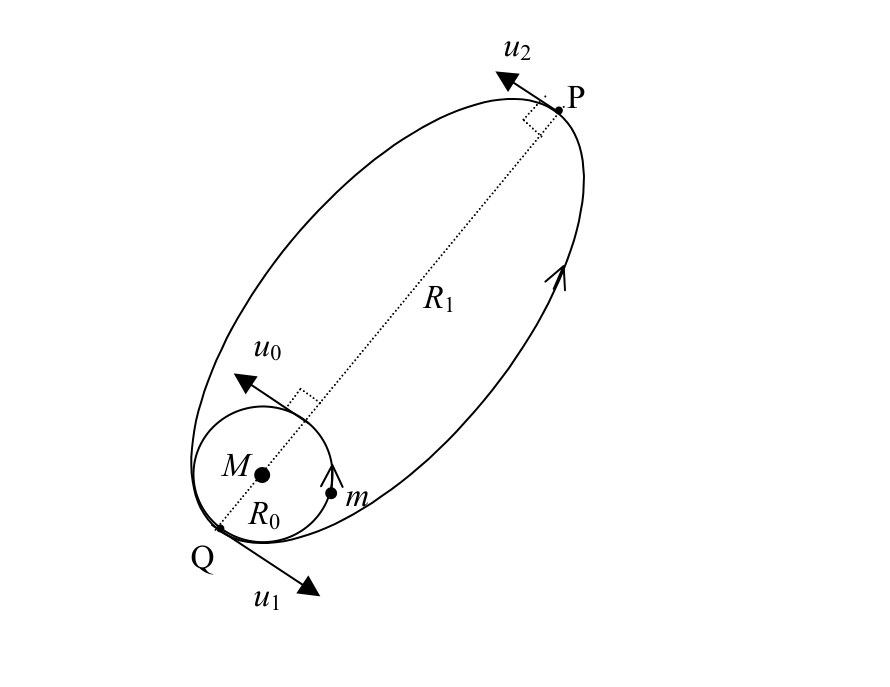
a) A satellite of mass is presently circling the Earth of mass in a circular orbit of radius . What is the speed () of mass in terms of , and the universal gravitation constant ?
(1 point)
b) We are to put this satellite into a trajectory that will take it to point P at distance from the centre of the Earth by increasing (almost instantaneously) its velocity at point Q from to . What is the value of in terms of , , ?
(2 points)
c) Deduce the minimum value of in term of that will allow the satellite to leave the Earth’s influence completely.
(1 point)
d) (Referring to part b.) What is the velocity () of the satellite at point P in terms of , , ?
(1 point)
e) Now, we want to change the orbit of the satellite at point P into a circular orbit of radius by raising the value of (almost instantaneously) to . What is the magnitude of in terms of , , ?
(1 point)
f)
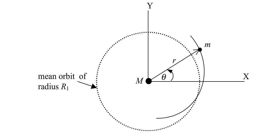
If the satellite is slightly and instantaneously perturbed in the radial direction so that it deviates from its previously perfectly circular orbit of radius , derive the period of its oscillation of about the mean distance .
Hint: Students may make use (if necessary) of the equation of motion of a satellite in orbit:
and the conservation of angular momentum:
(3 points)
g) Give a rough sketch of the whole perturbed orbit together with the unperturbed one.
(1 point)
Fonte: Testo (PDF) — p.1
Topic: Gravitation, Oscillations & Waves Metodi: Newton’s Law of Gravitation, Kepler’s Laws, Conservation of Energy, Differential Equations Competenze: Mathematical Modeling, Physical Reasoning Objects: Satellite, Planet
Transferimento in orbita del satellite
In un futuro prossimo potremmo partecipare noi stessi al lancio di un satellite che, dal punto di vista fisico, richiede solo l’uso di semplici meccaniche.
**a) ** Un satellite di massa sta attualmente girando intorno alla Terra di massa in un’orbita circolare di raggio . Qual è la velocità () della massa in termini di , e della costante gravitazionale universale ?
*(1 punto) *
**b) ** Dobbiamo mettere questo satellite in una traiettoria che lo porterà al punto P a distanza dal centro della Terra aumentando (quasi istantaneamente) la sua velocità al punto Q da a . Qual è il valore di in termini di , , ?
*(2 punti) *
**c) ** Riduzione del valore minimo di in termini di che consentirà al satellite di lasciare completamente l’influenza terrestre.
*(1 punto) *
**d) ** (Rifigurazione della parte b.) Qual è la velocità () del satellite al punto P in termini di , , ?
*(1 punto) *
**e) ** Ora, vogliamo cambiare l’orbita del satellite al punto P in un’orbita circolare di raggio aumentando il valore di (quasi istantaneamente) a . Qual è la magnitudine di in termini di , , ?
*(1 punto) *
f)
Se il satellite è leggermente e istantaneamente perturbato nella direzione radial in modo tale che si allontana dalla sua orbita perfettamente circolare di raggio , derivare il periodo di oscillazione di circa la distanza media .
Signore: Gli studenti possono utilizzare (se necessario) l’equazione di movimento di un satellite in orbita:
e la conservazione del momento angolare:
*(3 punti) *
**g) ** Fornire uno sketch approssimativo dell’intera orbita perturbata insieme a quella non perturbata.
*(1 punto) *
Fonte: Testo (PDF) — p.1
Topic: Gravitation, Oscillations & Waves Metodi: Newton’s Law of Gravitation, Kepler’s Laws, Conservation of Energy, Differential Equations Competenze: Mathematical Modeling, Physical Reasoning Objects: Satellite, Planet
Optical Gyroscope
In 1913 Georges Sagnac (1869-1926) considered the use of a ring resonator to search for the aether drift relative to a rotating frame. However, as often happen, his results turned out to be useful ways that Sagnac himself never dreamt of. One of those applications is the Fibre-Optic Gyroscope (FOG) which is based upon a simple phenomena, first observed by Sagnac. The essential physics associated with the Sagnac effect is due to the phase shift caused by two coherent beams of light being sent around a rotating ring of optical fibre in the opposite directions. This phase shift is also used to determine the angular speed of the ring.
As shown in a schematic diagram in Fig. 1, a light wave enters a circular optical fibre light path of radius at point P on the rotating platform with a uniform angular speed , in the clockwise direction. Here the light wave is split into two waves which travels in the opposite directions, clockwise (CW) and counter clockwise (CCW), through the ring. The refractive index of optical fibre material is . Assuming the light traveling inside the fibre-optic cable is a smooth circular path of radius .
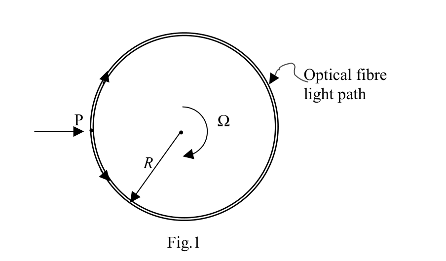
a) Practically, the orbital speed of the ring is much less than the speed of light such that , find the time difference where and denote the round-trip transit time of the CW and CCW beam respectively. Give your answer in term of area enclosed by the ring.
(2 points)
b) Find the optical path difference, , for the CW and CCW beams to complete one round-trip of the light within the rotating ring.
(2 points)
c) For a circular fibre-optic of radius, m, what is the maximum value of for the rotation of the earth? Given .
(1 point)
d) In part b), the measurement could be amplified by increasing number of turns in fibre-optic coil, , find the phase difference, , for lights to complete the turns.
(1 point)
The second scheme of the Optical Gyroscope is Ring Laser Gyroscope (RLG). This could be accomplished by the inclusion of active laser cavity into an equilateral triangular ring, of total length , as illustrated in Fig.2. The laser source here will generate two amplified coherent light sources propagating in the opposite directions. In order to sustain the laser oscillation in this triangular ring resonator, the perimeter of the ring must be equal to the integer multiple of wavelength . Etalon, additional component inserted into the ring, is possible to cause frequency selective losses in the ring resonator, so that the undesired modes can be damped and suppressed.
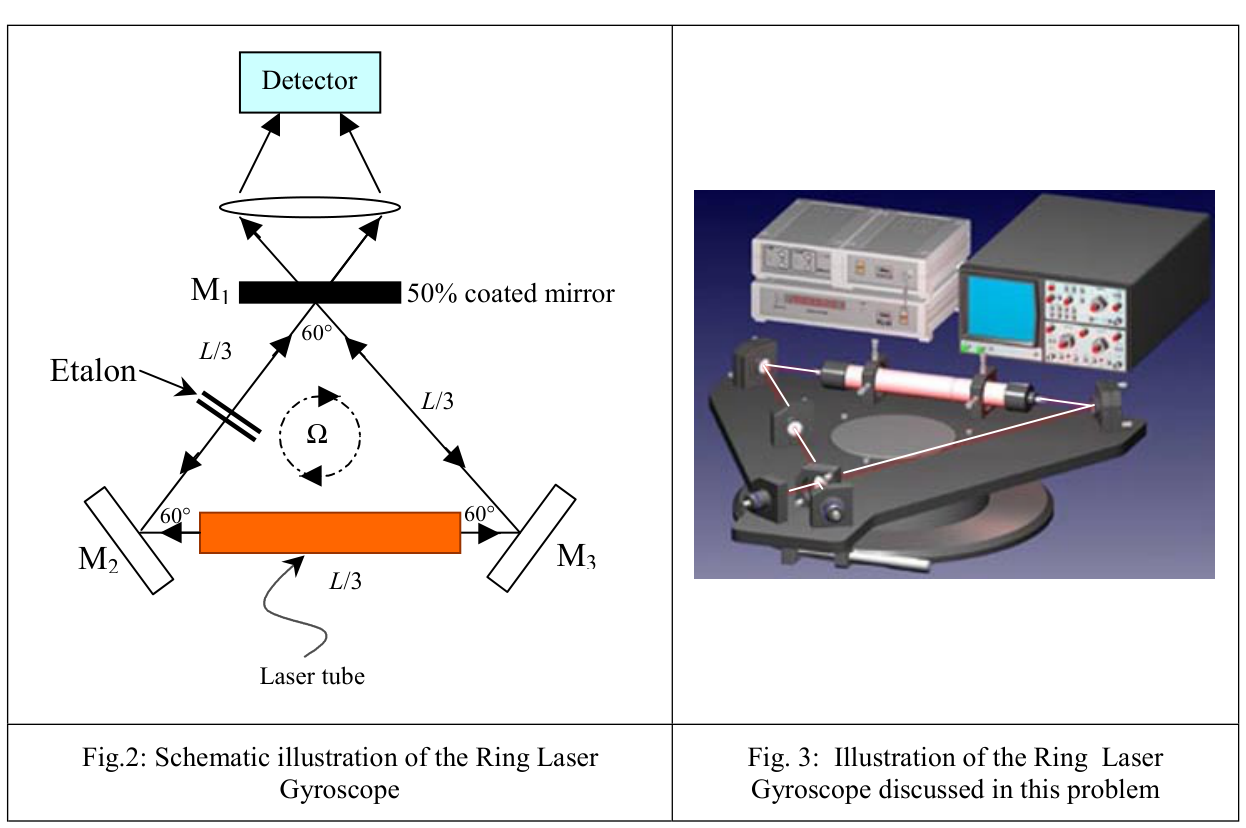
Fig.2: Schematic illustration of the Ring Laser Gyroscope
Fig. 3: Illustration of the Ring Laser Gyroscope discussed in this problem
e) Find the time difference of the transit in clockwise and counterclockwise, , for the case of the triangular ring as shown in the figure 2. Give the answer in terms of and the area enclosed by the ring. Show that this result is the same as that of the circular ring.
(2 points)
f) If the ring is rotating with an angular frequency as shown in Fig. 2, there will be frequency difference between CW and CCW measurements. What is the observed beat frequency, , between the CW and CCW beams in terms of , , .
(2 points)
Fonte: Testo (PDF) — p.1
Topic: Wave Optics, Special Relativity Metodi: Interference & Diffraction Analysis, Approximation & Series Expansion, Physical Modeling Competenze: Mathematical Modeling, Physical Reasoning Objects: —
Girocopia ottica
Nel 1913 Georges Sagnac (1869-1926) considerò l’uso di un risonatore anello per cercare la deriva dell’etere relativa a un telaio rotante. Tuttavia, come spesso accade, i suoi risultati si sono rivelati utili come non si sarebbe mai immaginato. Una di queste applicazioni è il Giroscopio a Fibre-Optico (FOG), che si basa su un semplice fenomeno, osservato per la prima volta da Sagnac. La fisica essenziale associata all’effetto Sagnac è dovuta al cambiamento di fase causato da due fasci di luce coerenti che vengono inviati intorno a un anello rotante di fibra ottica nelle direzioni opposte. Questo spostamento di fase viene utilizzato anche per determinare la velocità angolare dell’anello.
Come mostrato in un diagramma schematico in Figura. 1, un’onda luminosa entra in un percorso circolare di luce in fibra ottica di raggio al punto P della piattaforma rotante con una velocità angolare uniforme , in senso orario. Qui l’onda luminosa è divisa in due onde che viaggiano nelle direzioni opposte, nel senso orario (CW) e nel senso contro orario (CCW), attraverso l’anello. L’indice di rifrazione del materiale in fibra ottica è . Supponendo che la luce che viaggia all’interno del cavo a fibra ottica sia un percorso circolare liscio di raggio .
**a) ** In pratica, la velocità orbitale dell’anello è molto inferiore alla velocità della luce, in modo che , trovi la differenza di tempo dove e indicano rispettivamente il tempo di transito di andata e ritorno del fascio CW e del fascio CCW. Rispondi in termini di superficie connessa all’anello.
*(2 punti) *
**b) ** Trova la differenza di percorso ottico, , per i fasci CW e CCW per completare un viaggio di ritorno della luce all’interno dell’anello rotante.
*(2 punti) *
**c) ** Per una fibra ottica circolare di raggio m, qual è il valore massimo di per la rotazione della terra? Con .
*(1 punto) *
**d) ** Nella parte b), la misurazione potrebbe essere amplificata aumentando il numero di giri in bobina a fibra ottica, , trovare la differenza di fase, , per le luci per completare le giri.
*(1 punto) *
Il secondo schema del giroscopio ottico è il giroscopio laser anello (RLG). Questo potrebbe essere ottenuto mediante l’inserimento di una cavità laser attiva in un anello triangolare equilaterale, di lunghezza totale , come illustrato nella figura 2. La sorgente laser qui genererà due sorgenti di luce coerenti amplificate che si propagano nelle direzioni opposte. Per sostenere l’oscillazione laser in questo risonatore anello triangolare, il perimetro dell’anello deve essere uguale al multiplo intero della lunghezza d’onda . Etalon, componente aggiuntivo inserito nell’anello, può causare perdite selettive di frequenza nel risonatore anello, in modo da poter ammortizzare e sopprimere le modalità indesiderate.
Fig.2: illustrazione schematica del giroscopio laser anello
Fig. 3: Illustrazione del Giroscopio Laser Ring discusso in questo problema
**e) ** Trova la differenza di tempo del transito in senso orario e in senso contrario, , per il caso dell’anello triangolare come mostrato nella figura 2. Rispondi in termini di e di area connessa all’anello. Mostrare che questo risultato è lo stesso di quello dell’anello circolare.
*(2 punti) *
**f) ** Se l’anello ruota con una frequenza angolare come mostrato nella figura. 2, ci sarà una differenza di frequenza tra le misurazioni CW e CCW. Qual è la frequenza di battito osservata, , tra i fasci CW e CCW in termini di , , .
*(2 punti) *
Fonte: Testo (PDF) — p.1
Topic: Wave Optics, Special Relativity Metodi: Interference & Diffraction Analysis, Approximation & Series Expansion, Physical Modeling Competenze: Mathematical Modeling, Physical Reasoning Objects: —
Plasma Lens
The physics of the intense particle beams has a great impact not only on the basic research but also the applications in medicine and industry. The plasma lens is a device to provide an ultra-strong final focus at the end of the linear colliders. To appreciate the possibilities of the plasma lens it is quite natural to compare this with the usual magnetic and electrostatic lenses. In magnetic lenses, focusing capability is proportional to the magnetic field gradient. The practical upper limit of the quadrupole focusing lens is in the order of T/m, while for plasma lens having density of cm, its focusing capability is equivalent to a magnetic field gradient of T/m (about four orders of magnitude more than that of a magnetic quadrupole lens).
In what follows, we will illuminate why the intense relativistic particle beams could produce self-focusing beams and do not blow themselves apart in free space.
a) Consider a long cylindrical electron beam of uniform number density and average speed (both quantities in laboratory frame). Derive the expression for the electric field at a point at distance from the central axis of the beam using classical electromagnetics.
(1 point)
b) Derive the expression for the magnetic field at the same point as in a).
(2 points)
c) What is then the net outward force on the electron in the electron beam passing that point?
(1 point)
d) Assuming that the expression obtained in c) is applicable at relativistic velocities, what will be the force on the electron as approaches speed of light , where
(1 point)
e) If the electron beam of radius enters into a plasma of uniform density (the plasma is an ionized gas of ions and electrons with equal charge density), what will be the net force on the stationary plasma ion at distance outside the electron beam long after the beam entering the plasma. You may assume that the density of the plasma ions remains constant and the cylindrical symmetry is maintained.
(3 points)
f) After long enough time, what is the net force on an electron at distance from the central axis of the beam in the plasma, assuming provided that the density of the plasma ions remains constant and the cylindrical symmetry is maintained?
(2 points)
Fonte: Testo (PDF) — p.1
Topic: Electromagnetism, Special Relativity Metodi: Gauss’s Law, Ampère’s Law, Lorentz Force Analysis, Symmetry Argument Competenze: Physical Reasoning, Mathematical Modeling Objects: Particle Beam, Electron
Lens di plasma
La fisica dei fasci di particelle intense ha un grande impatto non solo sulla ricerca di base ma anche sulle applicazioni in medicina e industria. L’obiettivo plasma è un dispositivo per fornire un focus finale ultraforte alla fine dei collatori lineari. Per comprendere le possibilità della lente plasmatica è naturale confrontarla con le normali lenti magnetiche ed elettrostatiche. Nelle lenti magnetiche, la capacità di messa a fuoco è proporzionale al gradiente del campo magnetico. Il limite superiore pratico della lente di messa a fuoco quadrupolo è nell’ordine di T/m, mentre per la lente plasmatica con densità di cm, la sua capacità di messa a fuoco è equivalente a un gradiente di campo magnetico di T/m (circa quattro ordini di grandezza superiore a quello di una lente quadrupolo magnetica).
In quanto segue, illustreremo perché i fasci di particelle relativistici intensi potrebbero produrre fasci autofocali e non esplodere da soli nello spazio libero.
**a) ** Si consideri un lungo fascio di elettroni cilindrici di densità di numero uniforme e velocità media (ambedue quantità in telaio di laboratorio). Derivare l’espressione per il campo elettrico in un punto a distanza dall’asse centrale del fascio utilizzando l’elettromagnetismo classico.
*(1 punto) *
**b) ** Derivare l’espressione per il campo magnetico nello stesso punto di a).
*(2 punti) *
Qual è quindi la forza esterna netta sull’elettrone nel fascio di elettroni che passa da quel punto?
*(1 punto) *
**d) ** Supponendo che l’espressione ottenuta in c) sia applicabile a velocità relativistiche, quale sarà la forza sull’elettrone quando si avvicina alla velocità della luce , dove
*(1 punto) *
Se il fascio di elettroni di raggio entra in un plasma di densità uniforme (il plasma è un gas ionizzato di ioni ed elettroni con uguale densità di carica), qual è la forza netta sull’ ionetto di plasma stazionario * a distanza al di fuori del fascio di elettroni molto dopo che il fascio entra nel plasma. Si può presumere che la densità degli ioni plasmatici rimanga costante e la simmetria cilindrica sia mantenuta.
*(3 punti) *
Dopo un tempo sufficiente, qual è la forza netta di un elettrone a distanza dall’asse centrale del fascio nel plasma, supponendo , purché la densità degli ioni plasmatici rimanga costante e la simmetria cilindrica sia mantenuta?
*(2 punti) *
Fonte: Testo (PDF) — p.1
Topic: Electromagnetism, Special Relativity Metodi: Gauss’s Law, Ampère’s Law, Lorentz Force Analysis, Symmetry Argument Competenze: Physical Reasoning, Mathematical Modeling Objects: Particle Beam, Electron