Determination of Shapes by Reflection
Introduction
Direct visual observation is a method where human beings used their eyes to identify an object. However, not all things in life can be observed directly. For example, how can you tell the position of a broken bone? Is it possible to look at a baby inside a pregnant woman? How about identifying cancer cells inside a brain? All of these require a special technique involving indirect observation.
In this experiment, you are to determine the shape of an object using indirect observation. You will be given two closed cylindrical boxes and in each box, there will be an object with unknown shapes. Your challenge is to reveal the object without opening the box. The physics concepts for this experiment are simple, but creativity and some skills are needed to solve it.
Experiment
Apparatus
For this experiment, you will be given two sets of cylindrical boxes consisting of:
- An object with unknown shape to be determined (it is a simple geometrical object with either plane or cylindrical side).
- Closed cylindrical box with an angular scale on the top side (2a) and around its circumference (2b).
- A knob which you can rotate.
- A laser pointer.
- Spare batteries for the laser pointer.
- A ruler.
Experimental method
The students are to determine the shape of the object inside a closed cylindrical box. The diameter of the cylinder can be measured by a ruler. Students are not allowed to open the cylindrical box or break the seal to determine the shape of the object. The object is an 8-mm thick metal with its sides polished so that it can reflect light like a mirror. You can rotate the object using the knob on the top part of the cylinder. This will rotate the object inside the box along the same axis as the cylinder axis.
The laser pointer can be switched on by rotating its position. You can adjust the position of the light beam by rotating the laser pointer in either clockwise or anti-clockwise direction. The reflection of the laser beam from the laser pointer can be observed along the circumference of the closed cylinder. Measurement using the angular scale can be used. By rotating the knob on the upper part while the laser pointer is switched on, you will notice that as you rotate the object, the position of the reflected light from the object will change. If the light from the laser pointer dim or the laser pointer fail to work, ask the committee for replacement. By observing the correlation of the angular position of the object and the reflection of the laser beam, you should be able to determine the shape of the object.
For every object (the two objects are of different shapes):
- A. Draw a graph of: ‘reflection angle of the laser beam against the angular position of the object’ ( pt)
- B. Determine the number of sides (faces) in each object ( pt)
- C. Use data from the graphic to sketch the shape of the object and find the angular positions of changing sides correspond with the top angular scale ( pts)
For the object with fewer sides only:
- D. Draw rotating axis of the object and determine the distance to every sides ( pts)
- E. Determine the length of sides without error analysis; determine also the angles between neighboring sides. ( pts)
You must present your result on graph papers and try to deduce the mathematical equations to determine the shape of the object.
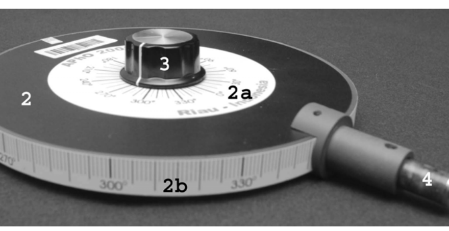 Apparatus: closed cylindrical box with the angular scale on the top side (2a) and around the circumference (2b); the unknown object (2) is inside, rotated by the knob (3); the laser pointer (4) shines onto it.
Remarks:
- One of the objects has only plane sides and the second object has one curved side.
- Sometimes you may get two reflections of the beam from the object.
- In case of a curved side the determination of the radius of curvature is not required but determination whether it is convex or concave with respect to the axis of rotation is necessary.
Fonte: Testo (PDF) — p.2 Topic: Geometric Optics, Mathematics Metodi: Ray Tracing, Snell’s Law, Experimental Data Analysis, Physical Modeling Competenze: Experimental Data Analysis, Measurement & Instrumentation, Diagrammatic Reasoning, Physical Reasoning Objects: Mirror, Container
Determinazione delle forme per riflessione
**Introduzione **
L’osservazione visiva diretta è un metodo in cui gli esseri umani usano gli occhi per identificare un oggetto. Tuttavia, non tutte le cose della vita possono essere osservate direttamente. Per esempio, come si può capire la posizione di un osso rotto? E’ possibile guardare un bambino dentro una donna incinta? Che ne dici di identificare le cellule tumorali all’interno del cervello? Tutti questi richiedono una tecnica speciale che coinvolga l’osservazione indiretta.
In questo esperimento, dovete determinare la forma di un oggetto utilizzando l’osservazione indiretta. Vi verranno date due scatole cilindriche chiuse e in ciascuna scatola, ci sarà un oggetto con forme sconosciute. La tua sfida è rivelare l’oggetto senza aprire la scatola. I concetti fisici per questo esperimento sono semplici, ma per risolverlo sono necessarie creatività e alcune competenze.
Esperimento
Apparecchi
Per questo esperimento, vi verranno date due serie di scatole cilindriche composte da:
- Un oggetto con forma sconosciuta da determinare (è un semplice oggetto geometrico con lato piatto o cilindrico).
- Cassa cilindrica chiusa con scala angolare sul lato superiore (2a) e intorno alla sua circonferenza (2b).
- Un pulsante che puoi girare.
- Un puntatore laser.
- Batterie di ricambio per il puntatore laser.
- Un governante.
Metoda sperimentale
Gli studenti devono determinare la forma dell’oggetto all’interno di una scatola cilindrica chiusa. Il diametro del cilindro può essere misurato con una regola. Gli studenti non possono aprire la scatola cilindrica o rompere il sigillo per determinare la forma dell’oggetto. L’oggetto è un metallo di 8 mm di spessore con i suoi lati lucidati in modo da poter riflettere la luce come uno specchio. Puoi ruotare l’oggetto usando il pulsante nella parte superiore del cilindro. Questo ruoterà l’oggetto all’interno della scatola lungo lo stesso asse del cilindro.
Il puntatore laser può essere acceso girando la sua posizione. Si può regolare la posizione del fascio di luce ruotando il puntatore laser in senso orario o in senso antiorario. Il riflesso del fascio laser del puntatore laser può essere osservato lungo la circonferenza del cilindro chiuso. Si può utilizzare la misurazione con la scala angolare. Girando il pulsante nella parte superiore mentre il puntatore laser è acceso, noterai che mentre ruoti l’oggetto, la posizione della luce riflessa dall’oggetto cambierà. Se la luce del puntatore laser si attenua o il puntatore laser non funziona, chiedere alla commissione di sostituirlo.
Per ogni oggetto (i due oggetti hanno forme diverse):
- A. Disegnare un grafico di: “angolo di riflessione del fascio laser contro la posizione angolare dell’oggetto” ( pt)
- B. Determina il numero di lati (facce) di ogni oggetto ( pt)
- C. Utilizzare i dati del grafico per disegnare la forma dell’oggetto e trovare le posizioni angolari dei lati in mutamento corrispondono alla scala angolare superiore ( pts)
Per l’oggetto con solo meno lati:
- D. Disegnare l’asse rotativo dell’oggetto e determinare la distanza verso ogni lato ( pts)
- E. Determina la lunghezza dei lati senza analisi di errori; determina anche gli angoli tra i lati vicini. ( pts)
Dovete presentare il risultato su carta grafica e cercare di dedurre le equazioni matematiche per determinare la forma dell’oggetto.
Apparecchio: scatola cilindrica chiusa con la scala angolare sul lato superiore (2a) e intorno alla circonferenza (2b); l’oggetto sconosciuto (2) è all’interno, girato dal pulsante (3); il puntatore laser (4) lo illumina.
**Rimarca: **
- Uno degli oggetti ha solo lati piani e il secondo oggetto ha un lato curvo.
- A volte si possono ottenere due riflessi del raggio dall’oggetto.
- In caso di lato curvo non è necessario determinare il raggio di curvatura, ma è necessario determinare se sia convexa o concava rispetto all’asse di rotazione.
Fonte: Testo (PDF) — p.2 Topic: Geometric Optics, Mathematics Metodi: Ray Tracing, Snell’s Law, Experimental Data Analysis, Physical Modeling Competenze: Experimental Data Analysis, Measurement & Instrumentation, Diagrammatic Reasoning, Physical Reasoning Objects: Mirror, Container
Magnetic Braking on an Inclined Plane
Introduction
When a magnet moves near a non-magnetic conductor such as copper and aluminum it experiences a dissipative force called magnetic braking force. In this experiment we will investigate the nature of this force.
The magnetic braking force depends on:
- the strength of the magnet, determined by its magnetic moment ();
- the conductivity of the conductor ();
- the size and geometry of both magnet and the conductor;
- the distance between the magnet and conducting surface (); and
- the velocity of the magnet () relative to the conductor.
In this experiment we will investigate the magnetic braking force dependencies on the velocity () and the conductor-magnet distance (). This force can be written empirically as:
F_{\text{mb}} = -k_0\, d^{\,p} v^{\,n} \tag{1}
where
- is an arbitrary constant that depends on , and geometry of the conductor and magnet which is fixed in this experiment.
- is the distance between the center of magnet to the conductor surface
- is the velocity of the magnet
- and are the power factors to be determined in this experiment
Experiment
In this experiment error analysis is required.
Apparatus
- Doughnut-shaped Neodymium Iron Boron magnet.
- Thickness: mm
- Outer diameter: mm
- The poles are on the flat faces as shown:
- Aluminum bar (2 pieces)
- Acrylic plate for the inclined plane with a linear track for the magnet to roll
- Plastic stand
- Digital stop watch
- Ruler
- Graphic papers (10 pieces)
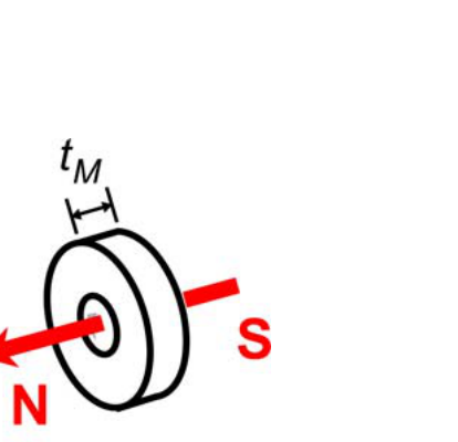 Doughnut-shaped magnet: the poles (N and S) are on the flat faces, with thickness measured along the axis.
Additional information:
- Local gravitational acceleration:
- Mass of the magnet: g
- North-South direction is indicated on the table.
You can read the operation manual of the stopwatch.
This problem is divided into two sections:
- (A) Setup and introduction
- (B) Investigation of the magnetic braking force
Remarks: Make sure that the plane is clean before your experiment.
Questions
Please provide sufficient diagrams in your answers so that your work can be understood clearly.
(A) Setup
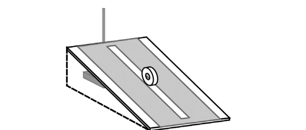 Figure 1. Inclined plane setup without aluminum bars.
Roll down the magnet along the track as shown. Choose a reasonably small inclination angle so that it does not roll too fast.
[1] As the magnet is very strong, it may experience significant torque due to interaction with earth’s magnetic field. It will twist the magnet as it rolls down and may cause significant friction with the track. What will you do to minimize this torque? Explain it using diagram(s). [1.0 pt]
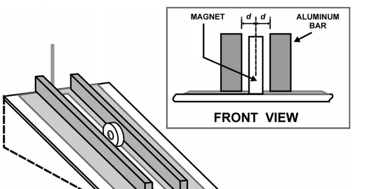 Figure 2. A complete setup with aluminum bars (with the front-view inset showing the magnet between two aluminum bars, each at distance from the center of the magnet).
Place the two aluminum bars as shown in Figure 2 with distance approximately mm. Remember that the distance is to the center of the magnet as shown in the inset of Figure 2.
Again release the magnet and let it roll. You should observe that the magnet would roll down much slower compared to the previous observation due to magnetic braking force.
[2] Provide diagram(s) of field lines and forces to describe the mechanism of magnetic braking. [1.0 pt]
(B) Investigation of the magnetic braking force
The experimental setup remains the same as shown in Figure 2 with the same magnet-conductor distance approximately mm (about 2 mm gap between magnet and conductor on each side).
[1] Keeping the distance fixed, investigate the dependence of magnetic braking force on velocity (). Determine the exponent of the speed dependence factor in Equation 1. Provide appropriate graph to explain your result. [4.0 pt]
Now vary the conductor-magnet distance () on both left and right. Choose a fixed and reasonably small inclination angle.
[2] Investigate the dependence of the magnetic braking force on conductor-magnet distance (). Determine the exponent of the distance dependence factor in Equation 1. Provide appropriate graph to explain your result. [4.0 pt]
Fonte: Testo (PDF) — p.5 Topic: Electromagnetic Induction, Newtonian Mechanics Metodi: Experimental Data Analysis, Graph Linearization, Lenz’s Law, Error Propagation Competenze: Experimental Data Analysis, Graph Linearization, Error Propagation, Measurement & Instrumentation Objects: Magnet, Inclined Plane
Freno magneto su un aereo inclinato
**Introduzione **
Quando un magnete si muove vicino a un conduttore non magnetico come il rame e l’alluminio, si verifica una forza dissipativa chiamata forza di frenata magnetica. In questo esperimento, esamineremo la natura di questa forza.
La forza di frenata magnetica dipende da:
- la forza del magnete, determinata dal suo momento magnetico ();
- la conducibilità del conduttore ();
- le dimensioni e la geometria sia del magnete che del conduttore;
- la distanza tra il magnete e la superficie conduttrice (); e
- la velocità del magnete () rispetto al conduttore.
In questo esperimento esamineremo le dipendenze della forza di frenata magnetica dalla velocità () e dalla distanza conduttore-magnete (). Questa forza può essere scritta empiricamente come:
F_{\text{mb}} = -k_0\, d^{\,p} v^{\,n} \tag{1}
dove
- è una costante arbitraria che dipende da , e dalla geometria del conduttore e del magnete che è fissata in questo esperimento.
- è la distanza tra il centro del magnete e la superficie del conduttore
- è la velocità del magnete
- e sono i fattori di potenza da determinare in questo esperimento
Esperimento
In questo esperimento è richiesta l’analisi degli errori.
Apparecchi
- Magnete di ferro borone di neodimio a forma di ciambella.
- Spessore: mm
- Diametro esterno: mm
- I pali sono su facce piatte come mostrato:
- Barretta in alluminio (2 pezzi)
- Piastra acrilica per il piano inclinato con una pista lineare per il rotolamento del magnete
- Scaffale in plastica
- Orologio di fermata digitale
- Reggente
- Paperi grafici (10 pezzi)
Magnete a forma di nocciolo: i poli (N e S) sono su facce piatte, con spessore misurato lungo l’asse.
**Informazioni aggiuntive: **
- Accelerazione gravitazionale locale:
- Massa del magnete: g
- La direzione Nord-Sud è indicata nella tabella.
Puoi leggere il manuale di funzionamento dell’orologio fermo.
Questo problema è diviso in due sezioni:
- A) Impostazione e introduzione
- (B) Indagine sulla forza di frenata magnetica
Rimarca: assicurati che l’aereo sia pulito prima del tuo esperimento.
Domande
Si prega di fornire sufficienti diagrammi nelle risposte affinché il vostro lavoro possa essere chiaramente compreso.
(A) Impostazione
Figura 1. Dispositivo di piano inclinato senza barre di alluminio.
Rolle il magnete lungo la pista come mostrato. Scelta un angolo di inclinazione ragionevolmente piccolo in modo da non ruotare troppo velocemente.
** [1] ** Poiché il magnete è molto forte, può sperimentare una coppia significativa a causa dell’interazione con il campo magnetico terrestre. Tornerà il magnete mentre ruota verso il basso e può causare un significativo attrito con la pista. Cosa farai per ridurre al minimo questa coppia? Spiegalo usando diagrammi(). [1.0 pt]
Figura 2. Un’impostazione completa con barre di alluminio (con l’inserimento della vista anteriore che mostra il magnete tra due barre di alluminio, ciascuna a distanza dal centro del magnete).
Si collocano le due barre di alluminio come mostrato nella figura 2 con una distanza di circa mm. Ricorda che la distanza è al centro del magnete come mostrato nell’inserimento della figura 2.
Sgancia di nuovo il magnete e lascia che ruoli. Dovreste osservare che il magnete si rullava molto più lentamente rispetto all’osservazione precedente a causa della forza di frenata magnetica.
[2] Fornire diagrammi di linee di campo e forze per descrivere il meccanismo di frenata magnetica. [1.0 pt]
(B) Indagine sulla forza di frenata magnetica
L’impostazione sperimentale rimane la stessa di quanto mostrato nella figura 2 con la stessa distanza tra magnete e conduttori di circa mm (circa 2 mm di distanza tra magnete e conduttore su ciascun lato).
[1] Mantenendo fissa la distanza , si deve studiare la dipendenza della forza di frenata magnetica dalla velocità (). *Determine l’esponente del fattore di dipendenza dalla velocità * nell’equazione 1. Fornisci un grafico appropriato per spiegare il risultato. [4.0 pt]
Ora variare la distanza magnetico-conduttore () sia a sinistra che a destra. Scegli un angolo di inclinazione fisso e ragionevolmente piccolo.
[2] Investigare la dipendenza della forza di frenata magnetica dalla distanza conduttore-magnete (). *Determine l’esponente del fattore di dipendenza da distanza * nell’equazione 1. Fornisci un grafico appropriato per spiegare il risultato. [4.0 pt]
Fonte: Testo (PDF) — p.5 Topic: Electromagnetic Induction, Newtonian Mechanics Metodi: Experimental Data Analysis, Graph Linearization, Lenz’s Law, Error Propagation Competenze: Experimental Data Analysis, Graph Linearization, Error Propagation, Measurement & Instrumentation Objects: Magnet, Inclined Plane