Theoretical Problem 1 - Back-and-Forth Rolling of a Liquid-Filled Sphere (10 points)
Consider a sphere filled with liquid inside rolling back and forth at the bottom of a spherical bowl. That is, the sphere is periodically changing its translational and rotational direction. Due to the viscosity of the liquid inside, the movement of the sphere would be very complicated and hard to deal with. However, a simplified model presented here would be beneficial to the solution of such a problem.
Assume that a rigid thin spherical shell of radius and mass is fully filled with some liquid substance of mass , denoted as . has such a unique property that usually it behaves like an ideal liquid (i.e. without any viscosity), while in response to some special external influence (such as electric field) it transits to solid state immediately with the same volume; and once the applied influence removed, the liquid state recovers immediately. Besides, this influence does not give rise to any force or torque exerting on the sphere. This liquid-filled spherical shell (for convenience, called “the sphere” hereafter) is supposed to roll back and forth at the bottom of a spherical bowl of radius () without any relative slipping, as shown in the figure. Assume the sphere moves only in the vertical plane (namely, the plane of the figure), please study the movement of the sphere for the following three cases:
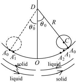
1. behaves as in ideal solid state, meanwhile contacts the inner wall of the spherical shell so closely that they can be taken as solid sphere as a whole of radius with an abrupt density change across the interface between the inside wall of the shell and .
(1) Calculate the rotational inertia of the sphere with respect to the axis passing through its center . (You are asked to show detailed steps.) (1.0 points)
(2) Calculate the period of the sphere rolling back and forth with a small amplitude without slipping at the bottom of the spherical bowl. (2.5 points)
2. behaves as an ideal liquid with no friction between and the spherical shell. Calculate the period of the sphere rolling back and forth with a small amplitude without slipping at the bottom of the spherical bowl. (2.5 points)
3. transits between ideal solid state and ideal liquid state.
Assume at time , the sphere is kept at rest, the line makes an angle ( rad) with the plumb line , where is the center of the spherical bowl. The sphere contacts the inner wall of the bowl at point , as shown in the figure. Release the sphere, it starts to roll left from rest. During the motion of the sphere from to its equilibrium position , behaves as ideal liquid. At the moment that the sphere passes through point , changes suddenly into solid state and sticks itself firmly on the inside wall of the sphere shell until the sphere reaches the left highest position . Once the sphere reaches , changes suddenly back into the liquid state. Then, the sphere rolls right; and changes suddenly into solid state and sticks itself firmly on the inside wall of the spherical shell again when the sphere passes through the equilibrium position . When the sphere reaches the right highest position , changes into liquid state once again. Then the whole circle repeats time after time. The sphere rolls right and left periodically but with the angular amplitude decreased time after time. The motion direction of the sphere is shown by curved arrows in the figure, together with the words “solid” and “liquid” showing corresponding state of . It is assumed that during such process of rolling back and forth, no any relative slide happens between the sphere and the inside wall of the bowl (or, alternatively, the bottom of the bowl can supply as enough friction as needed). Calculate the period of the sphere rolling right and left, and the angular amplitude of the center of the sphere, namely, the angle that the line makes with the vertical line when the sphere reaches the right highest position for the -th time (only is shown in the figure). (4.0 points)
Topic: Rotational Dynamics, Newtonian Mechanics Metodi: Torque & Angular Momentum Analysis, Simple Harmonic Motion Analysis, Conservation of Energy, Physical Modeling Competenze: Physical Reasoning, Mathematical Modeling Objects: Sphere Fonte: Testo (PDF) - p.1
**Problema teorico 1 - Rotolamento avanti e indietro di una sfera piena di liquidi (10 punti) **
Considerate una sfera piena di liquido che rotola avanti e indietro al fondo di una ciotola sferica. Cioè, la sfera sta cambiando periodicamente la sua direzione traslazionale e rotazionale. A causa della viscosità del liquido all’interno, il movimento della sfera sarebbe molto complicato e difficile da gestire. Tuttavia, un modello semplificato presentato qui sarebbe utile per risolvere tale problema.
Supponiamo che una rigida e sottile conchiglia sferica di raggio e massa sia completamente riempita di una sostanza liquida di massa , denominata . ha una proprietà unica tale da comportarsi di solito come un liquido ideale (cioè La temperatura di un’acqua di calore di 10 °C è inferiore a 10 °C, mentre la temperatura di calore di 1 °C è inferiore a 10 °C. Inoltre, questa influenza non dà luogo a alcuna forza o coppia che esercitino sulla sfera. Questo guscio sferico riempito di liquido (di seguito “la sfera”) dovrebbe rotolare avanti e indietro in fondo a una ciotola sferica di raggio () senza alcun scivolamento relativo, come mostrato nella figura. Supponendo che la sfera si muova solo nel piano verticale (cioè nel piano della figura), si prega di studiare il movimento della sfera per i seguenti tre casi:
1. si comporta come in stato solido ideale, mentre contatta la parete interna della conchiglia sferica così strettamente che possono essere prese come sfera solida in tutto il raggio con un brusco cambiamento di densità nell’interfaccia tra la parete interna della conchiglia e .
**(1) ** Calcolare l’inerzia di rotazione della sfera rispetto all’asse che attraversa il suo centro . (Si chiede di indicare i passaggi dettagliati.) (1.0 punti)
**(2) ** Calcolare il periodo della sfera che va avanti e indietro con una piccola amplitudine senza scivolare in fondo alla tazza sferica. (2,5 punti)
2. si comporta come un liquido ideale senza attrito tra e la conchiglia sferica. Calcolare il periodo della sfera che va avanti e indietro con una piccola amplitudine senza scivolare in fondo alla ciotola sferica. (2,5 punti)
**3. ** transiti tra stato solido ideale e stato liquido ideale.
Supponiamo che al tempo , la sfera sia tenuta in riposo, la linea fa un angolo ( rad) con la linea di piombo , dove è il centro della ciotola sferica. La sfera si trova nel punto nella parete interna della ciotola, come mostrato nella figura. Se rilasci la sfera, comincia a rotolare a sinistra. Durante il movimento della sfera da alla sua posizione di equilibrio , si comporta come liquido ideale. Nel momento in cui la sfera passa attraverso il punto , cambia improvvisamente in stato solido e si attacca saldamente alla parete interna della conchiglia della sfera fino a quando la sfera raggiunge la posizione più alta sinistra . Una volta che la sfera raggiunge , cambia improvvisamente di nuovo allo stato liquido. Poi, la sfera ruota a destra; e cambia improvvisamente in stato solido e si attacca saldamente al muro interno della conchiglia sferica di nuovo quando la sfera passa attraverso la posizione di equilibrio . Quando la sfera raggiunge la posizione più alta giusta , torna a diventare liquida. Poi l’intero cerchio si ripete una volta dopo l’altra. La sfera ruota periodicamente a destra e a sinistra, ma con l’ampiezza angolare diminuita di volta in volta. La direzione di movimento della sfera è indicata con frecce curve nella figura, insieme alle parole “solide” e “liquido” che mostrano lo stato corrispondente di . Si presume che durante tale processo di rotolamento avanti e indietro, non si verifichi alcun scivolo relativo tra la sfera e la parete interna della ciotola (o, in alternativa, il fondo della ciotola può fornire abbastanza attrito come necessario). Calcolare il periodo della sfera che ruota a destra e a sinistra e l’ampiezza angolare del centro della sfera, vale a dire l’angolo che la linea fa con la linea verticale quando la sfera raggiunge la posizione più alta a destra per la -tima volta (solo è mostrato nella figura). (4,0 punti)
Topic: Rotational Dynamics, Newtonian Mechanics Metodi: Torque & Angular Momentum Analysis, Simple Harmonic Motion Analysis, Conservation of Energy, Physical Modeling Competenze: Physical Reasoning, Mathematical Modeling Objects: Sphere Fonte: Testo (PDF) - p.1
2A. Optical properties of an unusual material (7 points)
The optical properties of a medium are governed by its relative permittivity () and relative permeability (). For conventional materials like water or glass, which are usually optically transparent, both of their and are positive, and refraction phenomenon meeting Snell’s law occurs when light from air strikes obliquely on the surface of such kind of substances. In 1964, a Russian scientist V. Veselago rigorously proved that a material with simultaneously negative and would exhibit many amazing and even unbelievable optical properties. In early 21st century, such unusual optical materials were successfully demonstrated in some laboratories. Nowadays study on such unusual optical materials has become a frontier scientific research field. Through solving several problems in what follows, you can gain some basic understanding of the fundamental optical properties of such unusual materials.
It should be noticed that a material with simultaneously negative and possesses the following important property. When a light wave propagates forward inside such a medium for a distance , the phase of the light wave will decrease, rather than increase, an amount of as what happens in a conventional medium with simultaneously positive and . Here, positive root is always taken when we apply the square-root calculation, while is the wave vector of the light. In the questions listed below, we assume that both the relative permittivity and permeability of air are equal to 1.
1.
(1) According to the property described above, assuming that a light beam strikes from air on the surface of such an unusual material with relative permittivity and relative permeability , prove that the direction of the refracted light beam depicted in Fig. 2-1 is reasonable. (1.2 points)
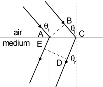 Fig. 2-1
(2) For Fig. 2-1, show the relationship between refraction angle (the angle that refracted beam makes with the normal of the interface between air and the material) and incidence angle . (0.8 points)
(3) Assuming that a light beam strikes from the unusual material on the interface between it and air, prove that the direction of the refracted light beam depicted in Fig. 2-2 is reasonable. (1.2 points)
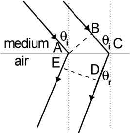 Fig. 2-2
(4) For Fig. 2-2, show the relationship between the refraction angle (the angle that refracted beam makes with the normal of the interface between two media) and the incidence angle . (0.8 points)
2. As shown in Fig. 2-3, a slab of thickness , which is made of an unusual optical material with , is placed in air, with a point light source located in front of the slab separated by a distance of . Accurately draw the ray diagrams for the three light rays radiated from the point source. (Hints: under the conditions given in this problem, no reflection would happen at the interface between air and the unusual material). (1.0 points)
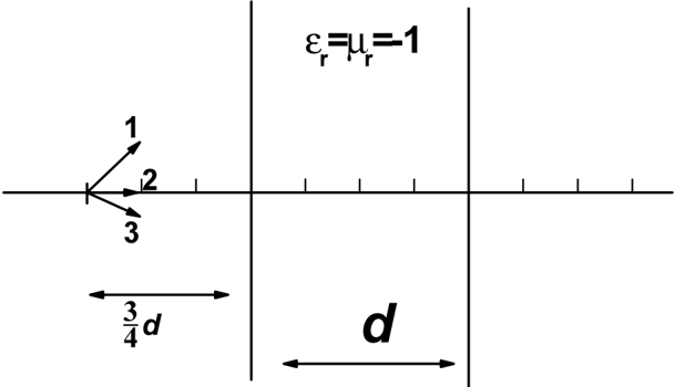 Fig. 2-3
3. As shown in Fig. 2-4, a parallel-plate resonance cavity is formed by two plates parallel with each other and separated by a distance . Optically one of the plates, denoted as Plate 1 in Fig. 2-4, is ideally reflective (reflectance equals to 100%), and the other one, denoted by Plate 2, is partially reflective (but with a high reflectance). Suppose plane light waves are radiated from a source located near Plate 1, then such light waves are multiply reflected by the two plates inside the cavity. Since optically the Plate 2 is not ideally reflective, some light waves will leak out of Plate 2 each time the light beam reaches it (ray 1, 2, 3, as shown in Fig. 2-4), while some light waves will be reflected by it. If these light waves are in-phase, they will interfere with each other constructively, leading to resonance. We assume that the light wave gains a phase of by reflection at either of the two plates. Now we insert a slab of thickness (shown as the shaded area in Fig. 2-4), made of an unusual optical material with , into the cavity parallel to the two plates. The remaining space is filled with air inside the cavity. Let us consider only the situation that the light wave travels along the direction perpendicular to the plates (the ray diagram depicted in Fig. 2-4 is only a schematic one), calculate all the wavelengths that satisfy the resonance condition of such a cavity. (Hints: under the condition given here, no reflection would occur at the interfaces between air and the unusual material). (1.0 points)
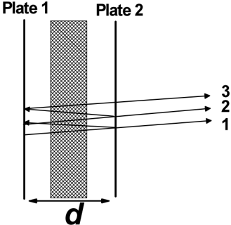 Fig. 2-4
4. An infinitely long cylinder of radius , made of an unusual optical material with , is placed in air, its cross section in plane is shown in Fig. 2-5 with the center located on axis. Suppose a laser source located on the axis (the position of the source is described by its coordinate ) emits narrow laser light along the direction. Show the range of , for which the light signal emitted from the light source can not reach the infinite receiving plane on the other side of the cylinder. (1.0 points)
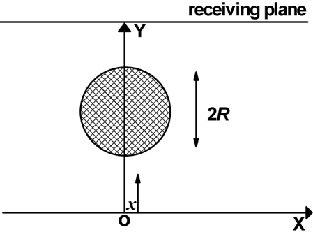 Fig. 2-5
2B. Dielectric spheres inside an external electric field (3 points)
By immersing a number of small dielectric particles inside a fluid of low-viscosity, you can get the resulting system as a suspension. When an external electric field is applied on the system, the suspending dielectric particles will be polarized with electric dipole moments induced. Within a very short period of time, these polarized particles aggregate together through dipolar interactions so that the effective viscosity of the whole system enhances significantly (the resulting system can be approximately viewed as a solid). This type of phase transition is called “electrorheological effect”, and such a system is called “electrorheological fluid” correspondingly. Such an effect can be applied to fabricate braking devices in practice, since the response time of such a phase transition is shorter than conventional mechanism by several orders of magnitude. Through solving several problems in the following, you are given a simplified picture to understand the inherent mechanism of the electrorheological transition.
1. When there are many identical dielectric spheres of radius immersed inside the fluid, we assume that the dipole moment of each sphere , is induced solely by the external field , independent of any of the other spheres (Note: ).
(1) When two identical small dielectric spheres exist inside the fluid and contact with each other, while the line connecting their centers makes an angle with the external field direction (see Fig. 2-6), write the expression of the energy of dipole-dipole interaction between the two small contacting dielectric spheres, in terms of , and . (Note: In your calculations each polarized dielectric sphere can be viewed as an electric dipole located at the center of the sphere) (0.5 points)
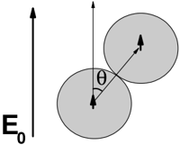 Fig. 2-6
(2) Calculate the dipole-dipole interaction energies for the three configurations shown in Fig. 2-7. (0.75 points)
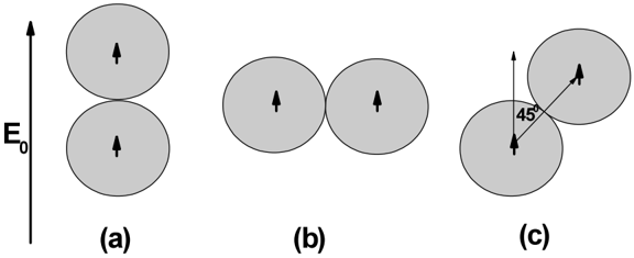 Fig. 2-7
(3) Identify which configuration of the system is the most stable one. (0.25 points) (Note: In your calculations each polarized dielectric sphere can be viewed as an electric dipole located at the center of the sphere, and the energy of dipole-dipole interaction can be expressed in terms of and .)
2. In the case that three identical spheres exist inside the fluid, based on the same assumption as in question 1,
(1) calculate the dipole-dipole interaction energies for the three configurations shown in Fig. 2-8; (0.9 points)
(2) identify which configuration of the system is the most stable one; (0.3 points)
(3) identify which configuration of the system is the most unstable one. (0.3 points) (Note: In your calculations each polarized dielectric sphere can be viewed as an electric dipole located at the center of the sphere, and the energy of dipole-dipole interaction can be expressed in terms of and .)
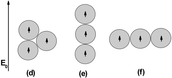 Fig. 2-8
Topic: Geometric Optics, Electrostatics Metodi: Snell’s Law, Ray Tracing, Superposition Principle, Electric Potential Method Competenze: Physical Reasoning, Diagrammatic Reasoning, Mathematical Modeling Objects: Lens, Sphere Fonte: Testo (PDF) - p.1
2A. Proprietà ottiche di un materiale insolito (7 punti)
Le proprietà ottiche di un mezzo sono determinate dalla sua relativa permitabilità () e dalla relativa permeabilità (). Per i materiali convenzionali come l’acqua o il vetro, che sono di solito otticamente trasparenti, sia il loro che il loro sono positivi, e il fenomeno di rifrazione conforme alla legge di Snell si verifica quando la luce dell’aria colpisce obliquamente la superficie di tali sostanze. Nel 1964, uno scienziato russo V. Veselago ha rigorosamente dimostrato che un materiale con simultaneamente e negativi avrebbe mostrato molte proprietà ottiche sorprendenti e anche incredibili. All’inizio del 21° secolo, tali materiali ottici insoliti furono dimostrati con successo in alcuni laboratori. Oggi lo studio di tali materiali ottici insoliti è diventato un campo di ricerca scientifica di frontiera. Risolvendo diversi problemi in quanto segue, si può ottenere una certa comprensione di base delle proprietà ottiche fondamentali di tali materiali insoliti.
Si deve notare che un materiale con simultaneamente negativo e possiede la seguente proprietà importante. Quando un’onda luminosa si propaga in avanti all’interno di tale mezzo per una distanza , la fase dell’onda luminosa diminuirà, piuttosto che aumentare, una quantità di come accade in un mezzo convenzionale con simultaneamente e positivi. Qui, la radice positiva viene sempre presa quando si applica il calcolo della radice quadrata, mentre è il vettore d’onda della luce. Nella domanda seguente, presumiamo che sia la relativa permissività che la permeabilità dell’aria siano uguali a 1.
1.
**(1) ** Secondo la proprietà descritta sopra, supponendo che un fascio luminoso colpisca dall’aria la superficie di un materiale così insolito con relativa permissività e relativa permeabilità , si dimostra che la direzione del fascio luminoso rifraccato raffigurata nella figura. Il 2-1 è ragionevole. 1,2 punti)
Fig. 2-1
**(2) ** Per la figura. 2-1, indicare la relazione tra l’angolo di rifrazione (angolo che il fascio rifraccato fa con la normalità dell’interfaccia tra aria e materiale) e l’angolo di incidenza . (0,8 punti)
**(3) ** Supponendo che un fascio luminoso colpisca dal materiale insolito all’interfaccia tra esso e l’aria, dimostrare che la direzione del fascio luminoso rifraccato raffigurata nella figura. 2-2 e’ ragionevole. 1,2 punti)
Fig. 2-2
**(4) ** Per la figura. 2-2, indicare la relazione tra l’angolo di rifrazione (angolo che il fascio rifraccato fa con la normalità dell’interfaccia tra due supporti) e l’angolo di incidenza . (0,8 punti)
2. Come mostrato nella figura. 2-3, una lastra di spessore , realizzata in un materiale ottico insolito con , viene collocata in aria, con una sorgente luminosa puntata situata davanti alla lastra separata da una distanza di . Disegnare con precisione i diagrammi dei raggi dei tre raggi luminosi irradiati dalla fonte di punto. (Signature: in condizioni indicate in questo problema, non si verificerebbe alcun riflesso all’interfaccia tra aria e materiale insolito). 1,0 punti)
Fig. 2-3
3. Come mostrato nella figura. 2-4, una cavità di risonanza della piastra parallela è formata da due piastre parallele tra loro e separate da una distanza . Opticamente una delle piastre, indicata come piastra 1 nella figura. 2-4, è idealmente riflettente (riflettività pari al 100%), e l’altra, indicata dalla piastra 2, è parzialmente riflettente (ma con una riflettività elevata). Supponiamo che le onde di luce a piano siano irradiate da una fonte situata vicino alla piastra 1, allora tali onde di luce sono moltiplicate riflesse dalle due piastre all’interno della cavità. Poiché il piatto 2 non è otticamente riflettente, alcune onde luminose usciranno dal piatto 2 ogni volta che il fascio luminoso lo raggiunge (ragio 1, 2, 3, come mostrato nella figura. 2-4), mentre alcune onde di luce saranno riflettute da esso. Se queste onde di luce sono in fase, interferiranno fra loro in modo costruttivo, portando a risonanza. Supponiamo che l’onda luminosa guadagni una fase di per riflessione in una delle due placche. Ora inserciamo una lastra di spessore (visto come la zona ombrata nella figura. 2-4), realizzato in un materiale ottico insolito con , nella cavità parallela alle due lastre. Lo spazio restante è pieno di aria all’interno della cavità. Consideriamo solo la situazione in cui l’onda di luce viaggia lungo la direzione perpendicolare alle placche (il diagramma dei raggi raffigurato in Figura. 2-4 è solo uno schematico), calcolare tutte le lunghezze d’onda che soddisfano la condizione di risonanza di tale cavità. (Insigni: in questa condizione non si verificerebbe alcun riflesso nelle interfacce tra aria e materiale insolito). 1,0 punti)
Fig. 2-4
Un cilindro infinitamente lungo di raggio , realizzato con un materiale ottico insolito con , è posto in aria, la sua sezione trasversale nel piano è mostrata nella figura. 2-5 con il centro situato sull’asse . Supponiamo che una sorgente laser situata sull’asse (la posizione della sorgente è descritta con la sua coordinata ) emetta una luce laser stretta lungo la direzione . Indicare la gamma di , per la quale il segnale luminoso emesso dalla fonte luminosa non può raggiungere il piano di ricezione infinito dall’altro lato del cilindro. 1,0 punti)
Fig. 2-5
2B. Sfere dielettriche all’interno di un campo elettrico esterno (3 punti)
Immergendo una serie di piccole particelle dielettriche all’interno di un fluido di bassa viscosità, si può ottenere il sistema risultante come sospensione. Quando viene applicato un campo elettrico esterno al sistema, le particelle dielettriche sospese saranno polarizzate con i momenti di dipole elettrici indotti. In un periodo molto breve, queste particelle polarizzate si aggregano attraverso interazioni dipolari in modo che la viscosità effettiva dell’intero sistema aumenta significativamente (il sistema risultante può essere considerato circa come un solido). Questo tipo di transizione di fase è chiamato “effetto elettorreeologico”, e un tale sistema è chiamato “fluido elettorreeologico” corrispondentemente. Tale effetto può essere applicato nella pratica alla fabbricazione di dispositivi di frenata, poiché il tempo di risposta di una tale transizione di fase è inferiore di diversi ordini di grandezza rispetto al meccanismo convenzionale. Risolvendo diversi problemi di seguito, si ottiene un quadro semplificato per comprendere il meccanismo intrinseco della transizione elettrorheologica.
Quando ci sono molte sfere dielettriche identiche di raggio immerse all’interno del fluido, presumiamo che il momento di dipole di ciascuna sfera , sia indotto esclusivamente dal campo esterno , indipendente da qualsiasi altra sfera (Nota: ).
**(1) ** Quando due piccole sfere dielettriche identiche esistono all’interno del fluido e contattano tra loro, mentre la linea che collega i loro centri fa un angolo con la direzione del campo esterno (vedi Figura. 2-6), scrivere l’espressione dell’energia di interazione dipolo-dipolo tra le due piccole sfere dielettriche in contatto, in termini di , e . (Nota: nei vostri calcoli ogni sfera dielettrica polarizzata può essere considerata come un dipolo elettrico situato al centro della sfera) (0,5 punti)
Fig. 2-6
**(2) ** Calcolare le energie di interazione di dipole-dipolo per le tre configurazioni mostrate nella figura. 2-7. (0,75 punti)
Fig. 2-7
**(3) ** Indicare quale configurazione del sistema sia la più stabile. (0,25 punti) (Nota: nei tuoi calcoli ogni sfera dielettrica polarizzata può essere vista come un dipolo elettrico situato al centro della sfera, e l’energia dell’interazione dipolo-dipolo può essere espressa in termini di e .)
2. Nel caso in cui all’interno del fluido esistano tre sfere identiche, basandosi sulla stessa ipotesi della domanda 1,
**(1) ** calcola le energie di interazione di dipole-dipole per le tre configurazioni mostrate nella figura. 2-8; (0,9 punti)
**(2) ** identificare quale configurazione del sistema sia la più stabile; (0,3 punti)
**(3) ** identificare quale configurazione del sistema sia la più instabile. (0,3 punti) (Nota: nei tuoi calcoli ogni sfera dielettrica polarizzata può essere vista come un dipolo elettrico situato al centro della sfera, e l’energia dell’interazione dipolo-dipolo può essere espressa in termini di e .)
Fig. 2-8
Topic: Geometric Optics, Electrostatics Metodi: Snell’s Law, Ray Tracing, Superposition Principle, Electric Potential Method Competenze: Physical Reasoning, Diagrammatic Reasoning, Mathematical Modeling Objects: Lens, Sphere Fonte: Testo (PDF) - p.1
3A. Average contribution of each electron to specific heat of free electron gas at constant volume (5 points)
1. According to the classical physics the conduction electrons in metals constitute free electron gas like an ideal gas. In thermal equilibrium their average energy relates to temperature, therefore they contribute to the specific heat. The average contribution of each electron to the specific heat of free electron gas at constant volume is defined as
where is the average energy of each electron. However the value of the specific heat at constant volume is a constant, independent of temperature. Please calculate and the average contribution of each electron to the specific heat at constant volume . (1.0 points)
2. Experimentally it has been shown that the specific heat of the conduction electrons at constant volume in metals depends on temperature, and the experimental value at room temperature is about two orders of magnitude lower than its classical counterpart. This is because the electrons obey the quantum statistics rather than classical statistics. According to the quantum theory, for a metallic material the density of states of conduction electrons (the number of electronic states per unit volume and per unit energy) is proportional to the square root of electron energy , then the number of states within energy range for a metal of volume can be written as
where is the normalization constant, determined by the total number of electrons of the system.
The probability that the state of energy is occupied by electron is
where J K is the Boltzmann constant and is the absolute temperature, while is called Fermi level. Usually at room temperature is about several eVs for metallic materials (1 eV J). is called Fermi distribution function shown schematically in the figure below.
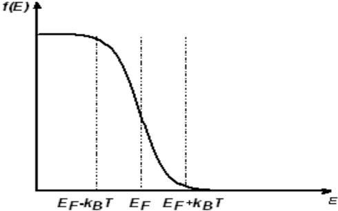
(1) Please calculate at room temperature according to . (3.5 points)
(2) Please give a reasonable explanation for the deviation of the classical result from that of quantum theory. (0.5 points)
Note: In your calculation the variation of the Fermi level with temperature could be neglected, i.e. assume , is the Fermi level at 0 K. Meanwhile the Fermi distribution function could be simplified as a linearly descending function within an energy range of around , otherwise either 0 or 1, i.e.
At room temperature , therefore calculation can be simplified accordingly. Meanwhile, the total number of electrons can be calculated at 0 K.
3B. The Inverse Compton Scattering (5 points)
By collision with relativistic high energy electron, a photon can get energy from the high energy electron, i.e. the energy and frequency of the photon increases because of the collision. This is so-called inverse Compton scattering. Such kind of phenomenon is of great importance in astrophysics, for example, it provides an important mechanism for producing X rays and rays in space.
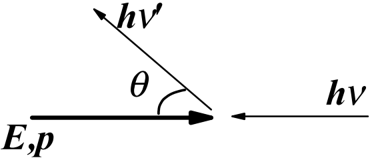
1. A high energy electron of total energy (its kinetic energy is higher than static energy) and a low energy photon (its energy is less than the static energy of an electron) of frequency move in opposite directions, and collide with each other. As shown in the figure below, the collision scatters the photon, making the scattered photon move along the direction which makes an angle with its original incident direction (the scattered electron is not shown in the figure). Calculate the energy of the scattered photon, expressed in terms of , , and static energy of the electron. Show the value of , at which the scattered photon has the maximum energy, and the value of this maximum energy. (2.4 points)
2. Assume that the energy of the incident electron is much higher than its static energy , which can be shown as , and that the energy of the incident photon is much less than , show the approximate expression of the maximum energy of the scattered photon. Taking and the wavelength of the incident visible light photon , calculate the approximate maximum energy and the corresponding wavelength of the scattered photon. (1.2 points)
Parameters: Static energy of the electron , Planck constant , and , where is the light speed in the vacuum.
3.
(1) A relativistic high energy electron of total energy and a photon move in opposite directions and collide with each other. Show the energy of the incident photon, of which the photon can gain the maximum energy from the incident electron. Calculate the energy of the scattered photon in this case. (0.7 points)
(2) A relativistic high energy electron of total energy and a photon, moving in perpendicular directions respectively, collide with each other. Show the energy of the incident photon, of which the photon can gain the maximum energy from the incident electron. Calculate the energy of the scattered photon in this case. (0.7 points)
Topic: Modern-Quantum Physics, Special Relativity Metodi: Statistical Averaging, Relativistic Energy-Momentum, Mass-Energy Equivalence, Photon Energy Relation Competenze: Physical Reasoning, Mathematical Modeling Objects: Electron, Photon Fonte: Testo (PDF) - p.1
3A. Contribuzione media di ciascun elettrone al calore specifico del gas elettronico libero a volume costante (5 punti)
Secondo la fisica classica gli elettroni di conduttività nei metalli costituiscono un gas elettronico libero come un gas ideale. In equilibrio termico la loro energia media si riferisce alla temperatura, quindi contribuiscono al calore specifico. Il contributo medio di ciascun elettrone al calore specifico del gas elettronico libero a volume costante è definito come
dove è l’energia media di ogni elettrone. Tuttavia, il valore del calore specifico a volume costante è costante, indipendente dalla temperatura. Calcolare e il contributo medio di ogni elettrone al calore specifico a volume costante . 1,0 punti)
2. Sperimentale è stato dimostrato che il calore specifico degli elettroni di conduttività a volume costante nei metalli dipende dalla temperatura, e il valore sperimentale a temperatura ambiente è di circa due ordini di magnitudo inferiore alla sua controparte classica. Questo perché gli elettroni obbediscono alle statistiche quantistiche piuttosto che alle statistiche classiche. Secondo la teoria quantistica, per un materiale metallico la densità degli stati di elettroni di conduttività (il numero di stati elettronici per unità di volume e per unità di energia) è proporzionale alla radice quadrata di energia elettronica , quindi il numero di stati all’interno della gamma di energia per un metallo di volume può essere scritto come
dove è la costante di normalizzazione, determinata dal numero totale di elettroni del sistema.
La probabilità che lo stato di energia sia occupato da un elettrone è
dove J K è la costante di Boltzmann e è la temperatura assoluta, mentre è chiamato livello di Fermi. Di solito a temperatura ambiente è di circa diversi eV per i materiali metallici (1 eV J). è chiamata funzione di distribuzione Fermi mostrata schematicamente nella figura seguente.
**(1) ** Calcolare a temperatura ambiente secondo . 3,5 punti)
**(2) ** Fornite una ragionevole spiegazione per la deviazione del risultato classico da quello della teoria quantistica. (0,5 punti)
Nota: nel vostro calcolo la variazione del livello di Fermi con la temperatura potrebbe essere trascurata, cioè supponiamo che , sia il livello di Fermi a 0 K. Nel frattempo la funzione di distribuzione di Fermi potrebbe essere semplificata come una funzione lineare in discesa entro un intervallo di energia di intorno a , altrimenti o 0 o 1, cioè.
A temperatura ambiente , il calcolo può essere quindi semplificato di conseguenza. Nel frattempo, il numero totale di elettroni può essere calcolato a 0 K.
3B. La dispersione inversa di Compton (5 punti)
Con una collisione con un elettrone di alta energia relativistica, un fotone può ottenere energia dall’elettrone di alta energia, cioè l’energia e la frequenza del fotone aumentano a causa della collisione. Questa è la cosiddetta dispersione inversa di Compton. Questo tipo di fenomeno è di grande importanza nell’astrofisica, ad esempio, fornisce un meccanismo importante per la produzione di raggi X e nel spazio.
1. Un elettrone ad alta energia di energia totale (la sua energia cinetica è superiore all’energia statica) e un fotone a bassa energia (la sua energia è inferiore all’energia statica di un elettrone) di frequenza si muovono in direzioni opposte e si collidono. Come mostrato nella figura di seguito, la collisione disperde il fotone, facendo muovere il fotone disperso in direzione che fa un angolo con la sua direzione incidentale originale (l’elettrone disperso non è mostrato nella figura). Calcolare l’energia del fotone sparso, espressa in , , e l’energia statica dell’elettrone. Indicare il valore di , al quale il fotone disperso ha l’energia massima, e il valore di questa energia massima. (4,4 punti)
2. Supponiamo che l’energia dell’elettrone incidente sia molto superiore alla sua energia statica , che può essere mostrata come , e che l’energia del fotone incidente sia molto inferiore a , mostrare l’espressione approssimativa dell’energia massima del fotone sparso. Prendendo e la lunghezza d’onda del fotone visibile incidente , calcolare l’energia massima approssimativa e la lunghezza d’onda corrispondente del fotone sparso. 1,2 punti)
Parametri: energia statica dell’elettrone , costante di Planck e , dove è la velocità della luce nel vuoto.
3.
**(1) ** Un elettrone di alta energia relativistica di energia totale e un fotone si muovono in direzioni opposte e si collidono tra loro. Mostra l’energia del fotone incidente, di cui il fotone può ottenere l’energia massima dall’elettrone incidente. Calcolare l’energia del fotone disperso in questo caso. (0,7 punti)
Un elettrone di alta energia relativistica di energia totale e un fotone, in movimento rispettivamente in direzioni perpendicolari, collidono tra loro. Mostra l’energia del fotone incidente, di cui il fotone può ottenere l’energia massima dall’elettrone incidente. Calcolare l’energia del fotone disperso in questo caso. (0,7 punti)
Topic: Modern-Quantum Physics, Special Relativity Metodi: Statistical Averaging, Relativistic Energy-Momentum, Mass-Energy Equivalence, Photon Energy Relation Competenze: Physical Reasoning, Mathematical Modeling Objects: Electron, Photon Fonte: Testo (PDF) - p.1