Problem 1: The Earth’s Horizontal Magnetic Field
This is to determine the horizontal component of the Earth’s magnetic field using small-amplitude oscillation of a cylindrical bar magnet. The magnet is to oscillate in the combined static fields of the Earth and that due to a square coil.
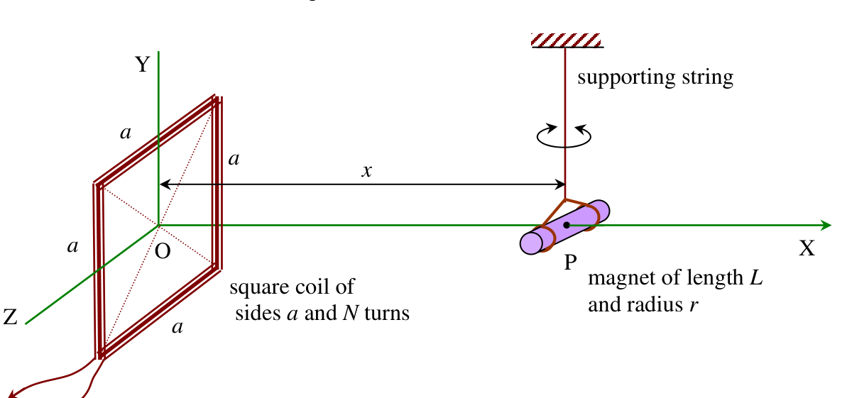 Figure 1
The experiment is to be done in three sections. Section I is a derivation of formulae to be used in Section III.
Apparatus
Each student is provided with apparatus as shown in Figure 2:
- a square coil of resistance and 130 turns
- a small cylindrical magnet of mass with nylon strings
- a voltmeter (for measuring the potential difference across the coil only)
- a power supply (placed under the table to avoid the interference of its magnetic field)
- a wooden stand
- a stop watch
- a ruler
- a protractor
- white label (you can write on it)
- color clay
- graph papers
- an electrical cord
Warning
Use the multi-meter to measure only the voltage difference of the coils. Using the multi-meter in other modes can destroy the power supply!!!
Section I
[1 point]
It is given here that the magnetic flux density at a perpendicular distance from the middle of a straight current element is
where henry per metre, the permeability of free space.
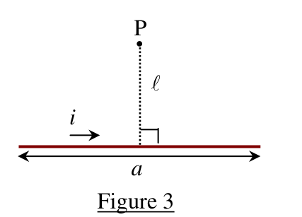 Figure 3
Use this expression to show that the expression for the magnitude of the magnetic flux density from the square coil at point P in Figure 1 is given by
It is also given here that the period of a small-amplitude oscillation of the magnet in the net magnetic field is
where is the magnetic moment of magnet with mass , and is its moment of inertia about the axis through its centre of mass
Section II
[0.8 point]
For the experiments in Section III you have to align the magnet in the position as shown in Figure 1. If the length of the string is too small, the torsion of the string cannot be neglected in the oscillation of the magnet. Perform appropriate measurements (say, oscillation of magnet in Earth’s magnetic field alone) to justify that we can ignore the torsion of the string. You are not required to plot a graph.
Section III
For the following experiments (in a, b, and c), you have to align the magnet in the position as shown in Figure 1. Measure and write down the value of the distance between the centre of the magnet and the top surface of the platform.
[0.2 point]
a) Coil’s magnetic field and Earth’s horizontal magnetic field in the same direction [5 points]
Warning
Please connect the coil to the power supply and leave it on for at least 5 minutes.
Measure periods of oscillation for different values of the combined field strength when the coil’s magnetic field and Earth’s magnetic field are in the same direction. Draw a straight line graph and compute the values of and the magnetic moment from this graph and estimate their errors.
b) Earth’s magnetic field only [1 point]
Use the value of from (a) and the period of oscillation of the magnet bar in the absence of the Coil’s magnetic field from Section II to calculate again the value for and estimate its error.
c) Coil’s magnetic field and Earth’s horizontal magnetic field in opposite directions [2 points]
By reversing the connection at the power supply, find the equilibrium position along the X-direction between Earth’s magnetic field and the opposing magnetic field from the coil. Use the value of to calculate again the value for and estimate its error.
Fonte: Testo (PDF) — p.1 Topic: Magnetism, Oscillations & Waves Metodi: Biot-Savart Law, Simple Harmonic Motion Analysis, Experimental Data Analysis, Graph Linearization Competenze: Experimental Data Analysis, Measurement & Instrumentation, Graph Linearization, Error Propagation Objects: Magnet, Coil
Problema 1: Campo Magnetico Orizzontale Terrestre
Questo è per determinare la componente orizzontale del campo magnetico terrestre utilizzando l’oscillazione a piccola amplitudine di un magnete a barre cilindriche. Il magnete oscilla nei campi statici combinati della Terra e questo a causa di una bobina quadrata.
Figura 1
L’esperimento sarà condotto in tre sezioni. La sezione I è una derivazione delle formule da utilizzare nella sezione III.
# # Apparecchiatura
Ogni studente è dotato di un apparecchio come mostrato alla figura 2:
- con una bobina quadrata di resistenza e 130 giri
- Magnete cilindrico di massa con fili di nylon
- un voltometro (solo per misurare la differenza di potenziale tra la bobina)
- un alimentatore (posso sotto il tavolo per evitare l’interferenza del suo campo magnetico)
- un appoggio in legno
- un stop watch
- un reggente
- un prolungatore
- etichetta bianca (potete scrivere su di essa)
- argile di colore
- carta grafica
- un cavo elettrico
Avvertimento
Utilizzare il multimetro per misurare solo la differenza di tensione delle bobine. Utilizzando il multimetro in altre modalità può distruggere l’alimentazione!!!
Sezione I
[1 punto]
Qui viene dato che la densità del flusso magnetico a una distanza perpendicolare dal centro di un elemento di corrente retta è
dove per metro, la permeabilità dello spazio libero.
Figura 3
Usare questa espressione per mostrare che l’espressione per la grandezza della densità del flusso magnetico dalla bobina quadrata al punto P nella figura 1 è data da
Si dice anche che il periodo di una oscillazione di piccola amplitudine del magnete nel campo magnetico netto è
dove è il momento magnetico del magnete con massa , e è il suo momento di inerzia intorno all’asse attraverso il suo centro di massa
Sezione II
[0,8 punto]
Per gli esperimenti della sezione III è necessario allineare il magnete nella posizione mostrata nella figura 1. Se la lunghezza della corda è troppo piccola, la torsione della corda non può essere trascurata nell’oscillazione del magnete. Eseguire misure appropriate (per esempio, oscillazione di magnete nel campo magnetico terrestre solo) per giustificare che possiamo ignorare la torsione della corda. Non è necessario disegnare un grafico.
Sezione III
Per i seguenti esperimenti (in a, b e c), è necessario allineare il magnete nella posizione mostrata nella figura 1. Misurare e registrare il valore della distanza tra il centro del magnete e la superficie superiore della piattaforma.
[0,2 punto]
a) Campo magnetico della bobina e campo magnetico orizzontale della Terra nella stessa direzione [5 punti]
Avvertimento
Si prega di collegare la bobina all’alimentazione e lasciarla accesa per almeno 5 minuti.
Misurare i periodi di oscillazione per i diversi valori della forza del campo combinato quando il campo magnetico della bobina e il campo magnetico terrestre sono nella stessa direzione. Disegnare un grafico di linea retta e calcolare i valori di e del momento magnetico da questo grafico e stimare i loro errori.
b) Solo il campo magnetico terrestre [1 punto]
Utilizzare il valore di di cui alla lettera a) e il periodo di oscillazione della barra magnetica in assenza del campo magnetico della bobina dalla sezione II per calcolare nuovamente il valore di e stimare il suo errore.
c) Campo magnetico della bobina e campo magnetico orizzontale della Terra in direzioni opposte [2 punti]
Invertendo la connessione all’alimentazione, trovare la posizione di equilibrio lungo la direzione X tra il campo magnetico terrestre e il campo magnetico opposto dalla bobina. Utilizzi il valore di per calcolare nuovamente il valore di e stimare il suo errore.
Fonte: Testo (PDF) — p.1 Topic: Magnetism, Oscillations & Waves Metodi: Biot-Savart Law, Simple Harmonic Motion Analysis, Experimental Data Analysis, Graph Linearization Competenze: Experimental Data Analysis, Measurement & Instrumentation, Graph Linearization, Error Propagation Objects: Magnet, Coil
Problem 2: Oscillation of Water-Filled Vessel
The student is required to perform non-destructive measurements in order to determine the thickness of an aluminium vessel whose cavity is completely filled with water. The aluminium vessel is composed of a cylinder and two end plates. The cylinder is of length and outer radius . The total length of the vessel is . The thickness of both end plates is (see Figure 1). You can neglect the error of this thickness. In this problem, please use gramme and centimetre as units for mass and length, respectively.
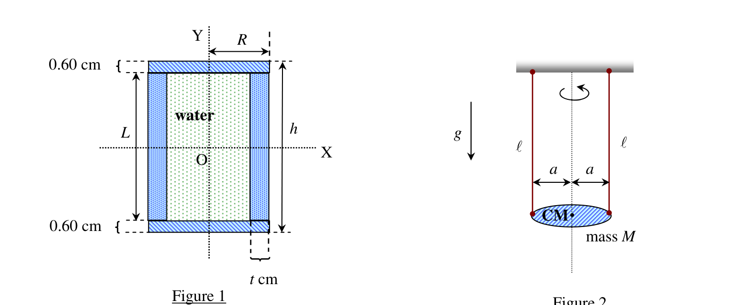 Figure 1 (left) and Figure 2 (right)
Figure 2 shows the so-called bifilar suspension of mass . The two strings are each of equal length . The period of a small-amplitude oscillation of is
where is the effective moment of inertia about the vertical axis through the centre of mass of and is the acceleration due to gravity at Bangkok ().
This experiment consists of two parts. Section I concerns a derivation of formulae and Section II concerns the actual experimentation.
Apparatus
Each student is provided with:
- a water-filled vessel
- a stand
- a stop watch
- a ruler
- a nylon string
- a protractor
- masking tapes
- a knife (not shown in the figure below)
Section I
[2.0 points]
The student is to derive expressions in terms of and the density of aluminium of the following quantities, [see Figure 1]
i) mass of the cylindrical body of the vessel, ii) mass of each end plate, iii) mass of water in the whole cavity, iv) the total mass of the water-filled vessel, and v) the effective moment of inertia, , about the Y-axis, of this water-filled vessel (see Figure 1), assuming that the water is ideal fluid.
Then perform measurements of . By substituting the values, derive expressions in terms of for the quantities i)–v) above. The aluminium density and the water density is .
Hint:
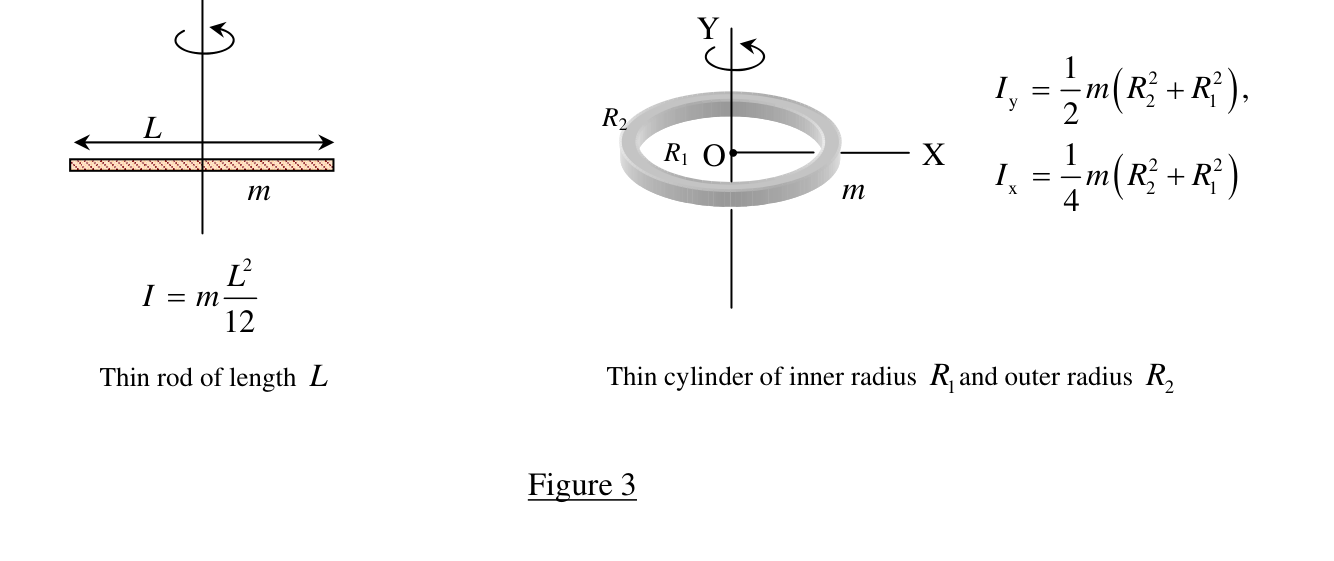 Figure 3 — Thin rod of length : . Thin cylinder of inner radius and outer radius : .
Section II
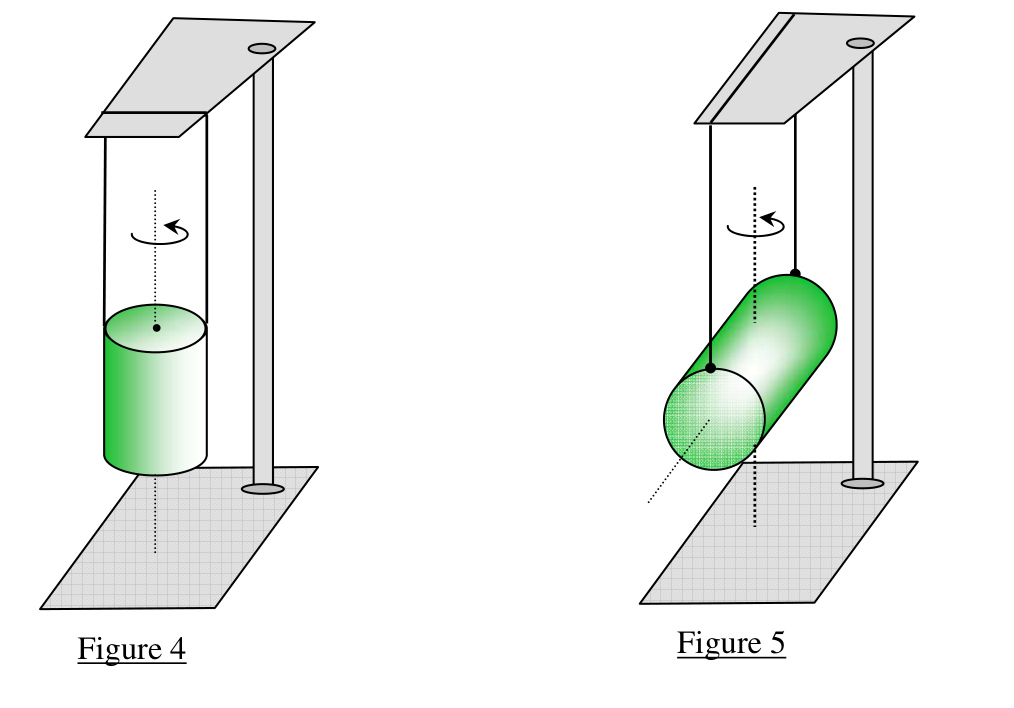 Figure 4 (left) and Figure 5 (right)
a) Angular oscillation about the axis of symmetry [4.0 points]
For one fixed value of , perform precise measurements of the period for a small-amplitude oscillation as in Figure 4. Then compute the value of the thickness of the cylindrical wall. Estimate the experimental error for the thickness. Compute also the values of , and using this value of .
b) Angular oscillation about the central axis perpendicular to the length [2.8 points]
Change the bifilar suspension of the vessel to that of Figure 5 and make similar measurements as in (a).
Then use the value of the period of oscillation just found together with the values of found in (a) to compute the value of the effective moment of inertia of the vessel about the X-axis (see Figure 2 and Figure 5).
Compute also the theoretical estimate of the value of based on the value of found in (a) assuming that the whole of the computed mass of water found in (a) is now constrained to take part in the oscillatory motion of the vessel.
c) Comparing experimental and theoretical values of the moment of inertia [1.2 points]
What is the difference between the values of and ?
Do you consider this difference statistically significant?
Estimate the percentage of the mass of water that takes part in the oscillatory motion in (b), assuming this water to be circular discs adhering to the end plates.
Hint:
Fonte: Testo (PDF) — p.5 Topic: Rotational Dynamics, Oscillations & Waves Metodi: Torque & Angular Momentum Analysis, Simple Harmonic Motion Analysis, Experimental Data Analysis, Error Propagation Competenze: Experimental Data Analysis, Measurement & Instrumentation, Error Propagation, Mathematical Modeling Objects: Cylinder, Container, String
**Problema 2: Oscillazione del vaso riempito di acqua **
Lo studente è tenuto a eseguire misure non distruttive per determinare lo spessore di un recipiente in alluminio la cui cavità è completamente riempita di acqua. Il recipiente in alluminio è composto da un cilindro e da due lastre finali. Il cilindro è di lunghezza e di raggio esterno . La lunghezza totale della nave è . Lo spessore di entrambe le lastre estremiste è (vedere figura 1). Puoi trascurare l’errore di questo spessore. In questo problema, si prega di utilizzare il grammo e il centimetro come unità di massa e lunghezza, rispettivamente.
*Figura 1 (sinistra) e 2 (destra) *
La figura 2 mostra la cosiddetta sospensione bifilare di massa . Le due stringhe sono di uguale lunghezza . Il periodo di un’oscillazione a piccola amplitudine di è
dove è il momento effettivo di inerzia intorno all’asse verticale attraverso il centro di massa di e è l’accelerazione dovuta alla gravità a Bangkok ().
Questo esperimento consiste in due parti. La sezione I riguarda la derivazione di formule e la sezione II riguarda la sperimentazione effettiva.
# # Apparecchiatura
Ogni studente ha:
- un recipiente riempito di acqua
- un stand
- un stop watch
- un reggente
- una corda di nylon
- un prolungatore
- nastri di maschera
- un coltello (non mostrato nella figura seguente)
Sezione I
[2,0 punti]
Lo studente deve derivare le espressioni **** in termini di e la densità di alluminio delle seguenti quantità, [vedi figura 1]
i) massa del corpo cilindrico della nave, ii) massa di ciascuna lastra terminale, iii) massa di acqua nell’intera cavità, iv) la massa totale del recipiente riempito di acqua, e v) il momento effettivo di inerzia, , circa l’asse Y di questo recipiente riempito di acqua (vedere figura 1), supponendo che l’acqua sia un fluido ideale.
Poi eseguire le misurazioni di . Substituendo i valori, ** espressioni derivate in termini di ** per i quantitativi i)v) di cui sopra. La densità di alluminio e la densità dell’acqua è .
**Signore: **
Figura 3 Sottile canna di lunghezza : . cilindro sottile di raggio interno e raggio esterno : .
Sezione II
*Figura 4 (sinistra) e 5 (destra) *
a) Oscillazione angolare intorno all’asse di simmetria [4,0 punti]
Per un valore fisso di , eseguire misure precise del periodo per un’oscillazione a piccola amplitudine come riportato nella figura 4. Calcolare quindi il valore dello spessore della parete cilindrica. Valutare l’errore sperimentale per lo spessore. Calcolare anche i valori di e utilizzando questo valore di .
b) Oscillazione angolare intorno all’asse centrale perpendicolare alla lunghezza [2,8 punti]
Cambiare la sospensione bifilare della nave a quella della figura 5 e effettuare misure simili alle indicate alla lettera a).
Per calcolare il valore del momento effettivo di inerzia della nave intorno all’asse X, utilizzare il valore del periodo di oscillazione appena trovato insieme ai valori di di cui alla lettera a) (vedi figura 2 e figura 5).
Calcolare anche la stima teorica del valore di sulla base del valore di riscontrato alla lettera a) supponendo che l’intera massa calcolata di acqua riscontrata alla lettera a) sia ora costretta a partecipare al movimento oscillatorio della nave.
c) Confronto dei valori sperimentali e teorici del momento di inerzia [1,2 punti]
Qual è la differenza tra i valori di e ?
Considerate questa differenza statisticamente significativa?
Estimare la percentuale di massa dell’acqua che partecipa al movimento oscillatorio nella lettera b), supponendo che l’acqua sia dischi circolari che si aderiscono alle lastre finali.
**Signore: **
Fonte: Testo (PDF) — p.5 Topic: Rotational Dynamics, Oscillations & Waves Metodi: Torque & Angular Momentum Analysis, Simple Harmonic Motion Analysis, Experimental Data Analysis, Error Propagation Competenze: Experimental Data Analysis, Measurement & Instrumentation, Error Propagation, Mathematical Modeling Objects: Cylinder, Container, String