Problem 1. A free conducting rod moves with constant speed to the right on top of conducting symmetrical tracks. The tracks are connected with a voltmeter VM in one of the edges, with length , and have an opening angle of . There is a changing homogeneous magnetic field which points outside the paper as shown in the figure. Answer: (a) Assuming that at we have , determine the voltage on the voltmeter as a function of time.
- B. At what time will it reach and ? What is the value of this voltage?
- C. Sketch a graph of the voltage of the voltmeter as a function of time. Figure 1: Problem 1
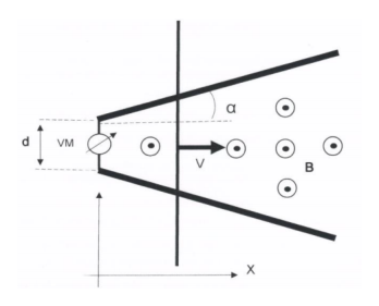 bacchetta conduttrice su binari con voltmetro
Topic: Electromagnetic Induction, Electromagnetism Metodi: Faraday’s Law of Induction, Calculus-Integration, Physical Modeling Competenze: Mathematical Modeling, Graph Linearization, Physical Reasoning Objects: Rod, Wire Fonte: Testo (PDF) — p.1
Problema 1. Una barra di conduttoria libera si muove a velocità costante a destra sopra le tracce di conduttoria simmetriche. Le tracce sono collegate ad una macchina elettronica voltometrica in uno dei bordi, con lunghezza e hanno un angolo di apertura di . C’è un magnetismo omogeneo che cambia campo che punta fuori dalla carta come mostrato nella figura. Risposta: (a) Supponendo che a abbiamo , determinare la tensione sul voltmeter come funzione
- Non è tempo.
- B. A che ora raggiungerà e ? Qual è il valore di questa tensione?
- C. Segnare un grafico della tensione del voltmeter in funzione del tempo. Figura 1: Problema 1
- balchetta conduttrice su binari con voltmetro *
Topic: Electromagnetic Induction, Electromagnetism Metodi: Faraday’s Law of Induction, Calculus-Integration, Physical Modeling Competenze: Mathematical Modeling, Graph Linearization, Physical Reasoning Objects: Rod, Wire Fonte: Testo (PDF) — p.1
Problem 2. One of the main effects of the gravitational attraction of the Earth-Moon system is the tidal effect. Well known on the surface of the Earth for the variation in the sea level along the lunar month, it also occurs below the crust with the deformation of Earth’s magma. Although there is no water on the surface of the Moon, the lunar magma also undergoes deformation due to Earth’s gravitational effect. In this problem we’re going to analyze how the tidal effect on the Moon connects the rotational speed to the angular motion around the Earth. Initially let the Moon have a rotational speed which is twice the actual rotational speed of the Moon. Let be the mass of the Earth, be the mass of the Moon and be its radius, be the gravitational constant, be the radius of the Moon’s orbit and the period of rotation of the Moon in its orbit. In the calculations below, use linear approximations for the appropriate functions. Provide results with 5% accuracy. Disregard the variation of Moon’s rotational energy due to the change in its shape.
- Assuming the Moon takes a circular orbit, determine the radius of that orbit and the potential energy, , of the Moon.
- To simplify the calculations, suppose that at time the entire Moon, including the crust, is transformed into lunar magma, forming a fluid with superficial pressure . What happens to the Moon at this instant? Does the mechanical energy of the system remain the same, increase or decrease? Why? Disregard the variation in the position of the Moon’s center of mass relative to the Earth.
- Approximate the ellipsoid to a geometry with three spheres with the same initial density as the moon, the largest having a radius and the two smaller having identical radius . Determine in terms of . Make a schematic drawing of the Moon model indicating the Earth’s position. Where does the energy needed to deform lunar magma come from? Determine that power.
- Describe the movement that the main axis of the lunar ellipsoid describes during a rotation of the Moon around the Earth. While the main axis describes this movement, the magma keeps itself in rotation around the axis itself, perpendicular to the main axis. Consider that at every rotation there is a constant power dissipation . Can be different from zero? Why?
If your answer was positive, in what situation would the dissipated energy be zero? And how many time would the Moon go around the Earth until it reaching that state? If the response was negative, determine the difference between the angular velocity of the plasma and that of the main axis of the ellipsoid. Express your results according to the potential energy of the real Moon.
Topic: Gravitation, Rotational Dynamics, Conservation of Energy Metodi: Newton’s Law of Gravitation, Torque & Angular Momentum Analysis, Conservation Laws Competenze: Physical Reasoning, Mathematical Modeling, Estimation & Approximation Objects: Planet Fonte: Testo (PDF) — p.1
Il problema 2. Uno degli effetti principali dell’attrazione gravitazionale del sistema Terra-Luna è il effetto delle maree. Ben noto sulla superficie terrestre per la variazione del livello del mare lungo la luna Il mese, si verifica anche sotto la crosta con la deformazione del magma terrestre. Anche se non c’è L’acqua sulla superficie della Luna, il magma lunare subisce anche deformazioni a causa dell’effetto gravitazionale della Terra. In questo problema analizzeremo come l’effetto delle maree sulla Luna collega velocità di rotazione al movimento angolare intorno alla Terra. Inizialmente, la Luna ha una velocità di rotazione. che è il doppio della velocità di rotazione reale della Luna. La massa della Terra è , essere la massa della Luna e essere il suo raggio, essere la costante gravitazionale, essere il raggio di l’orbita della Luna e il periodo di rotazione della Luna nella sua orbita. Nei calcoli di seguito, utilizzare approssimazioni lineari per le funzioni appropriate. Fornisce risultati con un’accuratezza del 5%. Non si deve considerare variazione dell’energia di rotazione della Luna a causa del cambiamento della sua forma.
- Supponendo che la Luna intraprenda un’orbita circolare, determinando il raggio di quella orbita e l’energia potenziale, , della Luna.
- Per semplificare i calcoli, supponiamo che al tempo l’intera Luna, compresa la crosta, sia trasformato in magma lunare, formando un fluido con pressione superficiale . Che succede alla Luna ?
- In questo istante? L’energia meccanica del sistema rimane la stessa, aumenta o diminuisce? - Perché? - Perché? Ignorare la variazione della posizione del centro di massa della Luna rispetto alla Terra.
- Approximare l’ellissoide a una geometria con tre sfere con la stessa densità iniziale che la la luna, la più grande con un raggio e le due più piccole con un raggio identico. Determina in termini di . Fare un disegno schematico del modello lunare che indica le Terre
- La posizione. Da dove viene l’energia necessaria per deformare il magma lunare? Determina quel potere.
- Descrivi il movimento che l’asse principale dell’ellissoide lunare descrive durante una rotazione di la Luna attorno alla Terra. Mentre l’asse principale descrive questo movimento, il magma si mantiene in rotazione intorno all’asse stesso, perpendicolare all’asse principale. Considerate che ad ogni rotazione c’è una discarica di potenza costante . può essere diverso da zero? - Perché? - Perché?
Se la tua risposta fosse positiva, in quale situazione l’energia dissipata sarebbe zero? E come Quante volte la Luna girerebbe intorno alla Terra fino a raggiungere questo stato? Se la risposta è stata negativa, determinare la differenza tra la velocità angolare del plasma e la velocità angolare del plasma. l’asse principale dell’ellipsoide. Esprimete i risultati in base all’energia potenziale del reale
- La Luna.
Topic: Gravitation, Rotational Dynamics, Conservation of Energy Metodi: Newton’s Law of Gravitation, Torque & Angular Momentum Analysis, Conservation Laws Competenze: Physical Reasoning, Mathematical Modeling, Estimation & Approximation Objects: Planet Fonte: Testo (PDF) — p.1
Problem 3. The figure shows an ellipse-shaped object with foci F1 and F2 positioned in a plane that contains the optical axis of a converging lens. Consider it to be translucent or with a slight inclination above the given plane, which allows the existence of rays leaving the illuminated surface which reach the lens and thus form the indicated figure as an image. We have indicated the center of the lens, but neither its angular position around it nor the focal length.
- A. Draw lines in the picture to determine the plane that contains the lens. Indicate it with a segment.
- B. Indicate the focal image point of the lens, i.e. the point where the rays parallel to the optical axis that come from the infinity should meet.
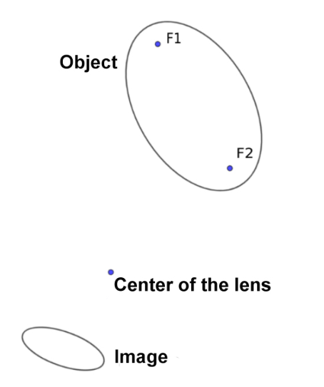 ellisse con fuochi F1 F2 oggetto immagine
Topic: Geometric Optics Metodi: Ray Tracing, Thin Lens & Mirror Equation, Symmetry Argument Competenze: Diagrammatic Reasoning, Physical Reasoning Objects: Lens Fonte: Testo (PDF) — p.2
Problema 3. La figura mostra un oggetto in forma di elipsina con foci F1 e F2 posizionati in un piano che contiene l’asse ottico di una lente convergente. Consideralo traslucente o con una leggera inclinazione sopra il piano dato, che consente l’esistenza di raggi che lasciano la superficie illuminata che raggiungono la lente e quindi formano la figura indicata come immagine. Abbiamo indicato il centro della lente, ma né la sua posizione angolare intorno a essa né la sua distanza focale.
- A. Disegnare linee nell’immagine per determinare il piano che contiene la lente. Indicare con un segmento.
- B. Indicare il punto focale dell’immagine dell’obiettivo, ovvero il punto in cui i raggi sono paralleli con il punto ottico Gli assi che provengono dall’infinito dovrebbero incontrarsi.
ellisse con fuochi F1 F2 oggetto immagine
Topic: Geometric Optics Metodi: Ray Tracing, Thin Lens & Mirror Equation, Symmetry Argument Competenze: Diagrammatic Reasoning, Physical Reasoning Objects: Lens Fonte: Testo (PDF) — p.2
Problem 4. A very small magnet A of mass is suspended horizontally by an in-extensible string of length . Another magnet B is also very small and is slowly approached to magnet A so that their horizontal axes are always aligned. See graph below. It is noted that when the distance between magnets reaches , and magnet A is at a distance from its initial position, the system remains in equilibrium. However, from this situation a tiny disturbance on the magnet A to the right causes the magnet to move abruptly towards B. Consider that the dependence of the magnetic interaction force on the distance between the magnets can be written as , where the signal depends on the relative orientation of the magnetos. Questions: (a) Determine and draw on the picture the horizontal forces exerted on the magnet A for a general equilibrium position. (b) Determine the values of and assuming that and . Figure 3: Problem 4
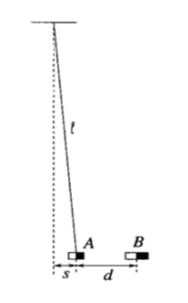 magnete A sospeso su filo con magnete B
Topic: Newtonian Mechanics, Magnetism Metodi: Free-Body Diagram, Physical Modeling, Approximation & Series Expansion Competenze: Mathematical Modeling, Physical Reasoning, Diagrammatic Reasoning Objects: Magnet, String Fonte: Testo (PDF) — p.2
Il problema 4. Un magnete molto piccolo A di massa è sospeso orizzontalmente da una corda inestensibile di lunghezza . Un altro magnete B è anche molto piccolo e si avvicina lentamente al magnete A in modo che i loro assi orizzontali sono sempre allineati. Vedi il grafico qui sotto. Si osserva che quando la distanza tra Magnete raggiunge e magnete A è a distanza dalla sua posizione iniziale, Il sistema rimane in equilibrio. Tuttavia, da questa situazione un piccolo disturbo sul magnete A La destra fa muovere bruscamente il magnete verso B. Considerate che la dipendenza del magnetico La forza di interazione sulla distanza tra i magneti può essere scritta come , dove il Il segnale dipende dall’orientamento relativo dei magneti. Domande:
- Determina e disegna sulle immagini le forze orizzontali esercitate sul magnete A per un posizione di equilibrio. b) Determinare i valori di e , supponendo che e . Figura 3: Problema 4
Magnete A sospeso su filo con magnete B
Topic: Newtonian Mechanics, Magnetism Metodi: Free-Body Diagram, Physical Modeling, Approximation & Series Expansion Competenze: Mathematical Modeling, Physical Reasoning, Diagrammatic Reasoning Objects: Magnet, String Fonte: Testo (PDF) — p.2
Problem 5. A small conductive bead of mass and load can slide freely without friction onto an insulating and circular thread of radius . An electric dipole with a very small electrical dipole moment is fixed in the center of the circle with the dipole’s axis in the circle plane in the diagram . Initially, the bead is fixed to the dipole’s symmetry plane as in the figure below with . Disregard the effect of gravity on the movement and assume that the electrical forces are much larger than the gravitational ones. Answer:
- A. Determine the bead’s speed after being released from the initial position.
- B. Determine the normal force of the insulating wire on the bead.
- C. At what point in the circle will the bead reach zero speed again after its release?
- D. What would the bead’s movement be like if the circular thread did not exist? Figure 4: Problem 5
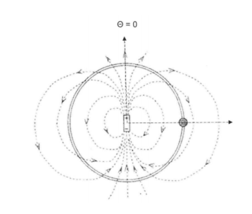 perla su filo circolare con dipolo elettrico
Topic: Electrostatics, Newtonian Mechanics Metodi: Electric Potential Method, Energy Conservation Method, Free-Body Diagram Competenze: Mathematical Modeling, Diagrammatic Reasoning, Physical Reasoning Objects: String Fonte: Testo (PDF) — p.3
Problema 5. Una piccola mancia conduttiva di massa e carico può scivolare liberamente senza attrito su un filo isolante e circolare di raggio . Un dipolo elettrico con un momento di dipolo elettrico molto piccolo è fissato al centro del cerchio con l’asse di dipolos nel piano del cerchio nel diagramma . Inizialmente, la perla è fissata al piano di simmetria del dipolo come nella figura seguente con . Ignorare l’effetto della gravità sul movimento e assumere che le forze elettriche sono molto più grandi della quelli gravitazionali. Risposta:
- A. Determina la velocità della mancia dopo essere stata rilasciata dalla posizione iniziale.
- B. Determina la forza normale del filo isolante sul fascio.
- C. A che punto del cerchio la mancia raggiungerà nuovamente velocità zero dopo il suo rilascio?
- D. Come sarebbe il movimento delle perle se il filo circolare non esistesse? Figura 4: Problema 5
Perla su filo circolare con dipolo elettrico
Topic: Electrostatics, Newtonian Mechanics Metodi: Electric Potential Method, Energy Conservation Method, Free-Body Diagram Competenze: Mathematical Modeling, Diagrammatic Reasoning, Physical Reasoning Objects: String Fonte: Testo (PDF) — p.3
Problem 6. When a metallic filament, such as tungsten, is heated to a high temperature it is observed an emission of electrons from the metal called thermionic emission of metals. This discovery was the basis of all electronics at the beginning of the 20th century with the development of electronic tubes, and even today we find it in various devices such as cathode ray tubes and magnetrons. To observe the thermionic current, the emitting filament (cathode) and the collector (anode) are placed in a vacuum environment to eliminate collisions of electrons with the atoms present in the environment. Under high temperature the emitting filament loses the electrons to the medium, where due to the effect of spatial charge near the filament, an electronic cloud is formed around the filament that eventually inhibits the emission of subsequent electrons. To prevent the formation of this spatial charge cloud, a potential difference is applied between the filament and the collector. The equation that defines the thermionic emission of the filament with respect to its temperature is called the Richardson equation:
Where is is the current density emitted by the filament, is the temperature in degrees Kelvin, and = work function of tungsten = . The temperature of the filament can be obtained by observing the linear variation of the resistivity with the temperature. The resistance is obtained by monitoring the voltage and current applied to the filament. See figure below. The resistivity of tungsten at room temperature of is , the filament has length and a diameter of . The temperature coefficient of tungsten can be assumed to be . On the other hand, the equation showing the effect of the accelerator potential between the cathode and the anode for thermionic current is called Child’s Law. The collected current density by the anode also depends on the geometry between the two electrodes, the most common being flat or cylindrical. For the case of cylindrical geometry, where the cathode is placed in the center of the cylinder and the anode in cylindrical form, we have:
Where is the current density collected by the anode, is the voltage difference applied between the cathode and the anode, is the internal diameter of the cylinder, and is the coefficient that depends on the ratio between the radii of the filament. Answer:
- A. Considering that the voltage and current observed on the respective meters in the filament indicate 2.0 V and 1.70 A, determine the temperature of the filament.
- B. For the temperature of the item (a) determine the saturation current you can obtain.
- C. Sketch the linear graph of voltage versus thermionic current observed on the meters of the collector. How can we verify whether the dependencies of these parameters are correct?
- D. How else can we determine the temperature of the filament using the data obtained in this work? And with this result, how can we verify the value of the work function of the filament? Figure 5: Problem 6
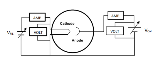 circuito emissione termioncia filamento
Topic: Circuits, Modern-Quantum Physics, Electrostatics Metodi: Experimental Data Analysis, Graph Linearization, Physical Modeling Competenze: Experimental Data Analysis, Graph Linearization, Mathematical Modeling Objects: Electron, Wire Fonte: Testo (PDF) — p.4
Problema 6. Quando un filamento metallico, come il tungsteno, viene riscaldato ad alta temperatura si osserva che una emissione di elettroni dal metallo chiamata emissione termionica dei metalli. Questa scoperta è stata la base di tutta l’elettronica all’inizio del XX secolo con lo sviluppo dei tubi elettronici, e anche oggi lo troviamo in vari dispositivi come tubi a raggi catodici e magnetroni. Per osservare le corrente termionica, il filamento emettente (catodo) e il collettore (anodo) sono collocati in vuoto ambiente per eliminare le collisioni di elettroni con gli atomi presenti nell’ambiente. Sotto alto la temperatura del filamento emettente perde gli elettroni al mezzo, dove a causa dell’effetto di La carica avvicina il filamento, si forma una nuvola elettronica intorno al filamento che infine inibisce il l’emissione di elettroni successivi. Per evitare la formazione di questa nube di carica spaziale, un potenziale si applica una differenza tra il filamento e il collettore. L’equazione che definisce la termionica l’emissione del filamento rispetto alla sua temperatura si chiama equazione Richardson:
Se è la densità di corrente emessa dal filamento, è la temperatura in gradi Kelvin, e = funzione di lavoro di tungsteno = . La temperatura della il filamento può essere ottenuto osservando la variazione lineare della resistività con la temperatura. Il la resistenza è ottenuta mediante il monitoraggio della tensione e della corrente applicate al filamento. Vedi la figura qui sotto. La resistività del tungsteno a temperatura ambiente di è , il filamento ha una lunghezza e diametro . Il coefficiente di temperatura del tungsteno può essere presunto a be . D’altra parte, l’equazione che mostra l’effetto del potenziale acceleratore tra la catode e l’anodo per la corrente termionica è chiamata legge di Child. La densità di corrente raccolta L’anodo dipende anche dalla geometria tra i due elettrodi, il più comune è piatto o cilindrica. Per la geometria cilindrica, in cui il catodo è collocato al centro della il cilindro e l’anodo in forma cilindrica, abbiamo:
Se è la densità di corrente raccolta dall’anodo, è la differenza di tensione applicata tra i la catode e l’anodo, è il diametro interno del cilindro e è il coefficiente che dipende dal rapporto tra i raggi del filamento. Risposta:
- A. Considerando che la tensione e la corrente osservati sui rispettivi contatori del filamento indicano 2,0 V e 1,70 A, si determina la temperatura del filamento.
- B. Per la temperatura del punto (a) determinare la corrente di saturazione che si può ottenere.
- C. Segna il grafico lineare della tensione contro la corrente termionica osservata sui contatori del collettore. Come possiamo verificare se le dipendenze di questi parametri sono corrette?
- D. Come possiamo altrimenti determinare la temperatura del filamento utilizzando i dati ottenuti in questo lavoro? E con questo risultato, come possiamo verificare il valore della funzione di lavoro del filamento? Figura 5: Problema 6
circuito emissione termoncia filamento
Topic: Circuits, Modern-Quantum Physics, Electrostatics Metodi: Experimental Data Analysis, Graph Linearization, Physical Modeling Competenze: Experimental Data Analysis, Graph Linearization, Mathematical Modeling Objects: Electron, Wire Fonte: Testo (PDF) — p.4
Problem 7. In a photoelectric effect experiment, a known wavelength radiation illuminates an electrode, called cathode (electron emitter), which has working function (energy that an electron inside the cathode needs so that it can beat the electron binding energy in the material). Depending on certain conditions of the incident wave, an electron (photoelectron) can be emitted and advance towards the anode (collector of electrons), which has a work function . The working function of the anode is greater than the of the cathode to avoid the emission of secondary electrons and new photoelectrons (because we are only interested in the photoelectrons emitted by the cathode). The electrical circuit of the experiment is shown in the layout below. In this figure the electrometer measures very low currents, in the order of . The multimeter measures the voltage and the DC applied to the two electrodes, and a potentiometer regulates the voltage applied to the electrodes of a battery, generally continuous. To obtain radiation of known wavelengths, we use a mercury (Hg) lamp with a diffraction network to obtain the spectral lines. In the chart below we list the main spectral lines emitted by mercury vapor. Note that the negative side of the source is connected to the anode, in order to repel the photoelectrons when a voltage is applied. And that the voltage observed between the electrodes is different from the voltage applied to the electrodes. And that the work function of the two electrodes must act differently for the photoelectrons. Answer: (a) What should be the greatest value of the cathode’s work function so that there is emission of photoelectrons for all the colours of the mercury spectra? (b) Considering that a photon h with the highest energy of the spectra has illuminated the cathode and that it has emitted photoelectrons of a certain energy, write the equation that relates the voltage observed in the multimeter with the other elements of the circuit, such as the wavelength incident on the cathode and any voltage provided by the potentiometer.
- C. Considering the item
- B. above, and assuming you are free to adjust the resistance in the potentiometer, explain and discuss in which voltage values we will have a reading of maximum, zero and minimum current in the electrometer? (d) How can we determine the work function of the anode according to the experimental data obtained in the previous items? (e) Sketch the current versus voltage curve for an emission spectrum, and discuss what kind of information we can get from this curve. Figure 6: Problem 7
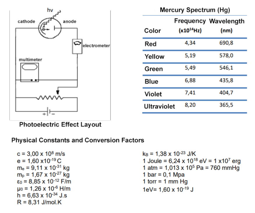 effetto fotoelettrico circuito e spettro mercurio
Topic: Modern-Quantum Physics Metodi: Photon Energy Relation, Energy Conservation Method, Experimental Data Analysis Competenze: Physical Reasoning, Experimental Data Analysis, Mathematical Modeling Objects: Photon, Electron, Battery, Diffraction Grating Fonte: Testo (PDF) — p.5
Problema 7. In un esperimento di effetto fotoelettrico, una conosciuta radiazione a lunghezza d’onda illumina un elettrodo, chiamato catodo (emittente di elettroni), che ha funzione di lavoro (energia che un elettrone all’interno la catode ha bisogno di poter superare l’energia di legame degli elettroni nel materiale). In base a determinate Le condizioni dell’onda incidentale, un elettrone (fototelettrone) può essere emesso e avanzare verso il Anodo (collettore di elettroni), che ha una funzione di lavoro . La funzione di lavoro dell’anodo è di dimensioni superiori a quelle del catodo per evitare l’emissione di elettroni secondari e di nuovi fotoelettroni (perché ci interessano solo i fotoelettroni emessi dal catodo). Il circuito elettrico di L’esperimento è mostrato nel layout di seguito. In questa figura l’elettrometro misura correnti molto basse, nell’ordine di . Il multimetro misura la tensione e la corrente corrente applicate ai due elettrodi, e un potenzimetro regola la tensione applicata agli elettrodi di una batteria, generalmente continua. Per ottenere radiazioni di lunghezze d’onda conosciute, usiamo una lampada a mercurio (Hg) con una rete di diffrazione per ottenere le linee spettrali. Nella tabella seguente elencamo le linee spettrali principali emesse dal vapore di mercurio. Si noti che il lato negativo della fonte è collegato all’anodo, al fine di respingere i fotoelettroni quando viene applicata una tensione. E che la tensione osservata tra gli elettrodi è diversa da quella osservata tra gli elettrodi la tensione applicata agli elettrodi. E che la funzione di lavoro dei due elettrodi deve agire in modo diverso per i fotoelettroni. Risposta: (a) Qual è il valore più elevato della funzione di lavoro della catode, in modo da produrre emissioni di fotoelettroni per tutti i colori dello spettro del mercurio? b) Considerando che un fotone h con la massima energia dello spettro ha illuminato il catodo e che ha emesso fotoelettroni di una certa energia, scrivete l’equazione che relaziona la tensione osservato nel multimetro con gli altri elementi del circuito, come l’incidente di lunghezza d’onda su il catodo e qualsiasi tensione fornita dal potenzimetro.
- C. Considerando la voce
- B. di cui sopra, e supponendo di poter regolare la resistenza nel potenzimetro, spiegare e discutere in quali valori di tensione avremo una lettura di massimo, zero e corrente minima nell’elettrometro? d) Come si può determinare la funzione di lavoro dell’anodo in base ai dati sperimentali ottenuti nei precedenti punti? (e) Segnare la curva di corrente contro tensione per uno spettro di emissioni e discutere quali informazioni possiamo ottenere da questa curva. Figura 6: Problema 7
*effetto circuito fotoelettrico e spettro mercurio *
Topic: Modern-Quantum Physics Metodi: Photon Energy Relation, Energy Conservation Method, Experimental Data Analysis Competenze: Physical Reasoning, Experimental Data Analysis, Mathematical Modeling Objects: Photon, Electron, Battery, Diffraction Grating Fonte: Testo (PDF) — p.5