E1 — Pendolo Magnetico (10 punti)
La frequenza di oscillazione di un pendolo può essere modificata da forze magnetiche tra il pendolo e il suo supporto. In questo esperimento studierete il moto del pendolo in un potenziale dato alla somma di termini di campo gravitazionale e magnetico, utilizzando l’impostazione mostrata in Fig. 3.
Apparecchiatura (vedi anche Fig. 3)
- A: Corpo del pendolo con supporti puntiformi e specchio per la misurazione dell’angolo
- B: Sostegno del pendolo con placchette di plastica rigide per appoggiare il pendolo e un profilo laser per la misurazione dell’angolo
- C: Guide per il supporto di magneti esterni
- D: 2 piccoli dipoli magnetici da fissare al corpo del pendolo
- E: 2 altri dipoli magnetici esterni identici (neri)
- F: 2 magneti esterni incogniti F1, F2 (blu, F2 è contrassegnato con un punto bianco a un estremo)
- G: Schermo per visualizzare lo spot del laser per la misurazione dell’angolo
- H: Cronometro
- I: Nastro adesivo
- J: Matita e righello
Domanda E1.1 — Masse (1.0 punti)
La massa totale del corpo del pendolo con attaccati i piccoli dipoli magnetici è . Misura sia che più accuratamente possibile.
Domanda E1.2 — Momenti di dipolo magnetico (4.0 punti)
Quando i magneti esterni sono posti vicino al pendolo magnetico, esso si muove in un potenziale dato dalla somma del campo gravitazionale e del campo magnetico. La frequenza del pendolo risultante, , può essere scritta come una funzione della frequenza naturale e dello “spostamento della frequenza magnetica” :
Nel caso in cui i dipoli magnetici esterni neri siano posizionati simmetricamente alla distanza vicino alla posizione di equilibrio del pendolo (vedi Fig. 1) e l’ampiezza delle oscillazioni sia piccola, lo “spostamento della frequenza magnetica” è:
dove è la permeabilità magnetica del vuoto, è il momento di inerzia del pendolo magnetico rispetto all’asse di rotazione, è il momento magnetico combinato dei magneti sul pendolo, è il momento magnetico di ogni dipolo esterno, e è la distanza dei magneti sul pendolo dall’asse di rotazione. Per la forza relativa dei momenti di dipolo si può ipotizzare . La gravità locale è .
a) Misurare le frequenze del pendolo per diverse distanze dei magneti, usando ampiezze di oscillazione molto piccole. Accertarsi di coprire tutto il range di frequenze accessibili.
b) Determinare la “magnetizzazione media” (momento magnetico per unità di massa) del materiale di cui sono fatti i magneti del pendolo e i dipoli magnetici esterni. Tracciare un grafico fatto bene dei dati per sostenere l’analisi.
Domanda E1.3 — I magneti esterni incogniti (3.0 punti)
Ciascuno dei due magneti esterni incogniti blu comprende diversi dipoli magnetici. I dipoli di F1 sono invertiti rispetto a quelli di F2. Lo spostamento di frequenza magnetica in una configurazione analoga a quella di Fig. 1 segue anch’esso una legge di potenza del tipo:
a) Misurare le frequenze del pendolo a diverse distanze , utilizzando ampiezze di oscillazione molto piccole. Scegliere le impostazioni che consentono di trovare lo spostamento della frequenza magnetica nel modo più accurato possibile.
b) Determinare l’esponente della legge di potenza .
c) Disegna uno schema della possibile configurazione interna di dipoli magnetici F1 ed F2 e motiva la tua scelta.
Domanda E1.4 — Pendolo non lineare (2.0 punti)
Riporta il montaggio alla configurazione utilizzata nella Domanda E1.2, con i dipoli magnetici esterni neri disposti come in Fig. 1. Utilizzando la Eq. 1, la frequenza delle piccole oscillazioni del pendolo può essere completamente azzerata, .
a) Determina con la massima precisione possibile la separazione del magnete necessaria per questo azzeramento completo.
b) Studia la dipendenza del periodo del pendolo dalla sua ampiezza quando è regolato sul migliore azzeramento che si è riusciti a ottenere. Suggerisci una dipendenza funzionale e confrontala con i tuoi dati. Discuti l’origine delle possibili discrepanze.
Topic: Oscillations & Waves, Magnetism, Newtonian Mechanics Metodi: Simple Harmonic Motion Analysis, Graph Linearization, Experimental Data Analysis, Physical Modeling, Error Propagation Competenze: Experimental Data Analysis, Graph Linearization, Measurement & Instrumentation Objects: Pendulum, Magnetic Dipole, Magnet Fonte: Testo (PDF) — p.1 Soluzione: Soluzioni (PDF)
The following table shows the results of the calculations:
The frequency of oscillation of a pendulum may be altered by magnetic forces between the pendulum and its support. In this experiment, you’ll study the motion of the pendulum in a potential given the sum of gravitational and magnetic field terms, using the setting shown in Fig. 3.
Equipment (see also Fig. 3)
- A: Pendulum body with pointed supports and mirror for measuring the angle
- B: Pendulum support with rigid plastic plates to support the pendulum and a laser profile for measuring the angle
- C: Guides for supporting external magnets
- D: 2 small magnetic dipoles to be attached to the body of the pendulum
- E: 2 other identical external magnetic dipoles (black)
- F: 2 unknown external magnets F1, F2 (blue, F2 is marked with a white dot at one end)
- G: Screen to display the laser spot for angle measurement
- H: Timer
- I: adhesive tape
- J: Pencil and pencil
The following table shows the number of samples taken:
The total mass of the pendulum body with attached small magnetic dipoles is . Measure both and as accurately as possible.
The following is the list of the parameters of the test:
When the external magnets are placed near the magnetic pendulum, it moves in a potential given by the sum of the gravitational field and the magnetic field. The resulting pendulum frequency, , may be written as a function of the natural frequency and the “magnetic frequency shift” :
In the case of black external magnetic dipoles positioned symmetrically at near the pendulum equilibrium position (see Fig. 1) and the range of oscillations is small, the ‘magnetic frequency shift’ is:
where is the magnetic permeability of the vacuum, is the moment of magnetic pendulum inertia with respect to the axis of rotation, is the combined magnetic moment of the pendulum magnets, is the magnetic moment of each external dipole, and is the distance of the magnets on the pendulum from the axis of rotation. The relative strength of the dipole moments can be assumed to be . The local gravity is .
(a) Measure the pendulum frequencies for different distances of magnets, using very small oscillation amplitudes. Make sure you cover the entire range of frequencies that you can access.
(b) Determine the ‘average magnetization’ (magnetic moment per unit mass) of the material of which the pendulum magnets and external magnetic dipoles are made. Draw a well-made graph of the data to support the analysis.
The following information is provided by the manufacturer:
Each of the two outer blue unconscious magnets comprises several magnetic dipoles. The dipole of F1 is inverted from that of F2. The magnetic frequency shift in a configuration analogous to Fig. 1 also follows a power law of the type:
(a) Measure the pendulum frequencies at different distances using very small oscillation amplitudes. Choose the settings that allow you to find the magnetic frequency shift as accurately as possible.
(b) Determine the power law exponent .
(c) Draw a diagram of the possible internal configuration of magnetic dipoles F1 and F2 and explain your choice.
The following is the list of the types of vehicles that are used in the manufacture of the product:
Returns the assembly to the configuration used in Question E1.2, with the external black magnetic dipoles arranged as in Figure 1. 1. Using the equation. 1, the frequency of small pendulum oscillations can be completely zeroed, .
(a) Determine with the greatest possible accuracy the magnet separation required for this complete zeroing.
(b) It studies the dependence of the period of the pendulum on its width when adjusted to the best freezing that has been achieved. Suggest a functional dependency and compare it to your data. Discuss the origin of the possible discrepancies.
Topic: Oscillations & Waves, Magnetism, Newtonian Mechanics Metodi: Simple Harmonic Motion Analysis, Graph Linearization, Experimental Data Analysis, Physical Modeling, Error Propagation Competenze: Experimental Data Analysis, Graph Linearization, Measurement & Instrumentation Objects: Pendulum, Magnetic Dipole, Magnet Fonte: Testo (PDF) — p.1 Soluzione: Soluzioni (PDF)
E2 — Scatola Nera Ottica (10 punti)
Il vostro compito è quello di determinare il contenuto di una scatola nera ottica senza aprirla. La scatola nera è dotata di quattro porte ottiche (A, B, C e D) per la luce e di due assi ottici (Fig. 2). Gli assi ottici sono perpendicolari tra loro. C’è al massimo un elemento ottico dietro ciascuna delle porte e un altro al centro della scatola. Per ruotare sul suo asse il laser è possibile utilizzare il laser e la rotella del supporto laser (su cui si possono apporre segni con una matita).
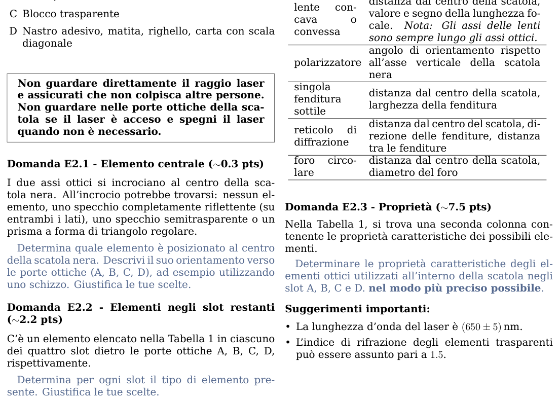
Materiale (vedi anche la Fig. 4)
- A: Scatola nera
- B: Modulo laser sul supporto con rotella
- C: Blocco trasparente
- D: Nastro adesivo, matita, righello, carta con scala diagonale
Domanda E2.1 — Elemento centrale (~0.3 punti)
I due assi ottici si incrociano al centro della scatola nera. All’incrocio potrebbe trovarsi: nessun elemento, uno specchio completamente riflettente (su entrambi i lati), uno specchio semitrasparente o un prisma a forma di triangolo regolare.
Determina quale elemento è posizionato al centro della scatola nera. Descrivi il suo orientamento verso le porte ottiche (A, B, C, D), ad esempio utilizzando uno schizzo. Giustifica le tue scelte.
Domanda E2.2 — Elementi negli slot restanti (~2.2 punti)
C’è un elemento elencato nella Tabella 1 in ciascuno dei quattro slot dietro le porte ottiche A, B, C, D, rispettivamente.
Determina per ogni slot il tipo di elemento presente. Giustifica le tue scelte.
Tabella 1: Elementi possibili negli slot della scatola nera
| Elemento | Parametro da determinare |
|---|---|
| Nessun elemento | c’è solo aria nella fessura |
| Specchio | angolo tra l’asse dello specchio e uno degli assi ottici |
| Prisma (triangolo regolare) | angolo tra uno dei suoi lati e uno degli assi ottici della scatola nera |
| Lente concava o convessa | distanza dal centro della scatola, valore e segno della lunghezza focale. Nota: gli assi delle lenti sono sempre lungo gli assi ottici. |
| Polarizzatore | angolo di orientamento rispetto all’asse verticale della scatola nera |
| Singola fenditura sottile | — |
 Fig. 4: materiale esperimento ottica
Fig. 1: dipoli magnetici esterni vista dall’alto
Fig. 3: montaggio pendolo magnetico
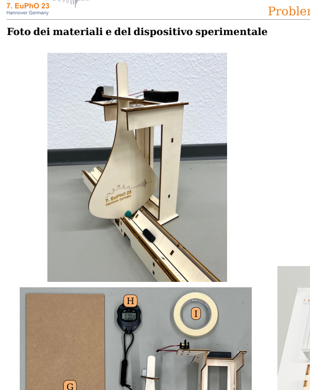 Fig. 2: disposizione scatola nera e slot
Topic: Geometric Optics, Wave Optics, Electromagnetism Metodi: Ray Tracing, Experimental Data Analysis, Physical Modeling, Thin Lens & Mirror Equation, Snell’s Law Competenze: Experimental Data Analysis, Diagrammatic Reasoning, Measurement & Instrumentation Objects: Mirror, Prism, Lens, Slit Fonte: Testo (PDF) — p.2 Soluzione: Soluzioni (PDF)
The following table shows the results of the tests:
Your task is to determine the contents of an optical black box without opening it. The black box is equipped with four optical doors (A, B, C and D) for light and two optical axes (Fig. 2). The optical axes are perpendicular to each other. There is at most one optical element behind each door and another at the center of the box. To rotate the laser on its axis, the laser and the wheel of the laser support (on which you can mark with a pencil) can be used.
The following table shows the results of the study: 4)
- A: Black box
- B: Laser module on wheel support
- C: Transparent block
- D: adhesive tape, pencil, ruler, paper with diagonal scale
The following table shows the results of the evaluation:
The two optical axes intersect at the center of the black box. At the intersection you may find: no element, a fully reflective mirror (on both sides), a semitravelling mirror or a prism in the shape of a regular triangle.
Determine which element is placed in the centre of the black box. Describe its orientation towards the optical doors (A, B, C, D), for example using a sketch. Justify your choices.
The following table shows the number of items in the remaining slots (~2.2 points)
There is an element listed in Table 1 in each of the four slots behind the optical doors A, B, C, D respectively.
Determine for each slot the type of element present. Justify your choices.
Table 1: Elements that are possible in black box slots
What is the size of the screen? |---|---| There’s nothing. There’s just air in the crack. ♪ Mirror ♪ The angle between the mirror axis and one of the optical axes ♪ Prism angle between one of its sides and one of the optical axes of the black box ♬ Lens convex or convex ♬ distance from the center of the box, value and focal length mark. Note: the lens axes are always along the optical axes. | ♬ Polarizer ♬ angle of orientation to the vertical axis of the black box ♬ ♪ And the only one that’s ever been broken ♪
The following table shows the results of the evaluation: The following information is provided for in Part A of Annex II:
The following table shows the results of the evaluation: 1: external magnetic dipoles seen from above*
The following table shows the results of the evaluation: The following is the list of the components used in the manufacture of the product:
The following table shows the results of the evaluation: 2: black box layout and slot*
Topic: Geometric Optics, Wave Optics, Electromagnetism Metodi: Ray Tracing, Experimental Data Analysis, Physical Modeling, Thin Lens & Mirror Equation, Snell’s Law Competenze: Experimental Data Analysis, Diagrammatic Reasoning, Measurement & Instrumentation Objects: Mirror, Prism, Lens, Slit Fonte: Testo (PDF) — p.2 Soluzione: Soluzioni (PDF)