Task 1 (0.5 pts) Terminals A1, A2, and A3 are connected to the Apotentiometer RP and an additional load resistor RL. Which of the schemes below corresponds to the circuit in the box? Determine the resistances RL and RP ; document the measurements made. A1 A2 RP RL 1 A3 A1 A2 RP RL 2 A3 A1 A2 RL RP 3 A3 Note The B-potentiometer is connected to terminals B1, B2, B3 in exactly the same way with the same resistances RL and RP , within manufacturing tolerances.
p.2 — Schema sinusoidi con ampiezza e periodo
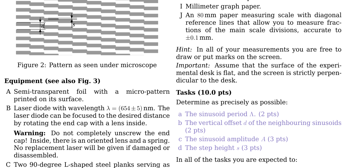
p.2 — Pattern visto al microscopio con passo s
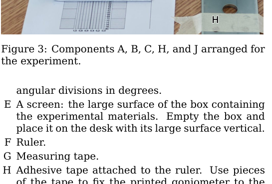
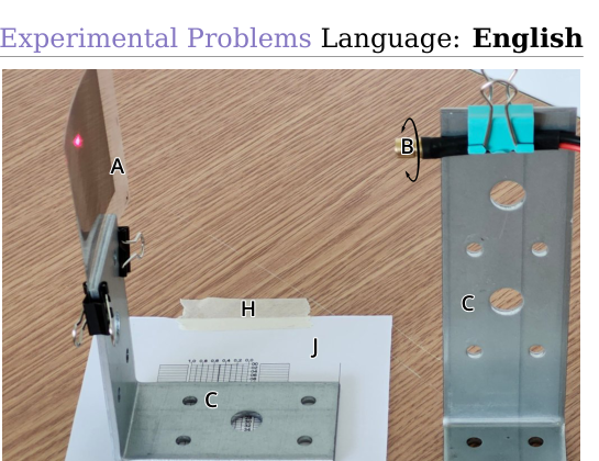
p.2 — Componenti A B C H J disposti per l’esperimento
Topic: Circuits Metodi: Equivalent Circuit Reduction, Kirchhoff’s Laws, Experimental Data Analysis Competenze: Diagrammatic Reasoning, Measurement & Instrumentation, Physical Reasoning Objects: Resistor Fonte: Testo (PDF) — p.1 Soluzione: Soluzioni (PDF)
The following information shall be provided: Terminals A1, A2, and A3 are connected to the Apotentiometer RP and an additional load resistor RL. Which of the schemes below corresponds to the circuit in the box? Determine the RL and RP; document the measurements made. A1 A2 RP RL 1 A3 A1 A2 RP RL 2 A3 A1 A2 RL RP 3 A3 Notes The B-potentiometer is connected to terminals B1, B2, B3 in exactly the same way with the same resistance RL and RP , within manufacturing The Commission has already adopted a proposal.
**p.2 ** Sinusoid scheme with width and period
**p.2 ** Pattern seen under the microscope with step s
**p.2 ** Components A B C H J prepared for the experiment
Topic: Circuits Metodi: Equivalent Circuit Reduction, Kirchhoff’s Laws, Experimental Data Analysis Competenze: Diagrammatic Reasoning, Measurement & Instrumentation, Physical Reasoning Objects: Resistor Fonte: Testo (PDF) — p.1 Soluzione: Soluzioni (PDF)
Task 2 - (0.5 pts) Sketch how the terminals have to be connected so that the neuron input voltages can be varied with the widest possible range.
Topic: Circuits Metodi: Physical Modeling, Equivalent Circuit Reduction Competenze: Diagrammatic Reasoning, Physical Reasoning Objects: — Fonte: Testo (PDF) — p.1 Soluzione: Soluzioni (PDF)
The following information is provided by the Commission: Sketch how the terminals have to be connected so That the neuron input voltages can be varied with the widest possible range.
Topic: Circuits Metodi: Physical Modeling, Equivalent Circuit Reduction Competenze: Diagrammatic Reasoning, Physical Reasoning Objects: — Fonte: Testo (PDF) — p.1 Soluzione: Soluzioni (PDF)
Task 3 - (1.5 pts) Devise (and document) a strategy allowing you to find the combination of input voltages x1 and x2 that maximizes the output voltage y with the least possible number of measurements, irrespectively of with which set of input voltages you start the search. Determine this maximal voltage ymax that will be henceforth used as an approximation for the amplitude A, and document your measurements.
Topic: Circuits Metodi: Experimental Data Analysis, Physical Modeling Competenze: Experimental Data Analysis, Estimation & Approximation, Measurement & Instrumentation Objects: — Fonte: Testo (PDF) — p.1 Soluzione: Soluzioni (PDF)
The Commission shall adopt delegated acts in accordance with Article 21 of the Financial Regulation. Devise (and document) a strategy allowing you to Find the combination of input voltages x1 and x2 that maximizes the output voltage y with the least possible number of measurements, irrespectively of with Which set of input voltages you start the search. Determine this maximum voltage ymax that will be henceforth used as an approximation for the amplitude A, and document your measurements.
Topic: Circuits Metodi: Experimental Data Analysis, Physical Modeling Competenze: Experimental Data Analysis, Estimation & Approximation, Measurement & Instrumentation Objects: — Fonte: Testo (PDF) — p.1 Soluzione: Soluzioni (PDF)
Task 4 - (3.5 pts) Determine the weights w1, w2 and the bias b. Describe your measurements and document your data in a table. Estimate w1, w2, and b by using a graphical approach. Training involves optimizing the network weights to achieve desired functionality. This allows ANNs to approximate arbitrary functions. For each of the following tasks you have to approximate a different function of a single input voltage using the given equipment. Make sure that the input and output that you define are clearly marked in your circuits.
Topic: Circuits Metodi: Kirchhoff’s Laws, Graph Linearization, Experimental Data Analysis Competenze: Graph Linearization, Experimental Data Analysis, Mathematical Modeling Objects: — Fonte: Testo (PDF) — p.1 Soluzione: Soluzioni (PDF)
The Commission shall adopt delegated acts in accordance with Article 21 of Regulation (EC) No 1299/2001. Determine the weights w1, w2 and the bias b. Describe your measurements and document your data in a table. Estimate w1, w2, and b using a graphical approach. Training involves optimizing the network weights to achieve the desired functionality. This allows ANNs to The following shall be added to the list of the following: For each of the following tasks you have to approximate to different function of a single input voltage using the given equipment. Make sure that the input and output that You define are clearly marked in your circuits.
Topic: Circuits Metodi: Kirchhoff’s Laws, Graph Linearization, Experimental Data Analysis Competenze: Graph Linearization, Experimental Data Analysis, Mathematical Modeling Objects: — Fonte: Testo (PDF) — p.1 Soluzione: Soluzioni (PDF)
Task 5 - (1.5 pts) Connect the terminal X1 directly to +V. Design a circuit to approximate the function y5(x)
(w2x/2 + b5), where x is the voltage applied to your newly defined input terminal. Determine b5 theoretically. Implement the circuit, take measurements and verify that your setup works as expected. Validate the value of b5 from your data.
Topic: Circuits Metodi: Kirchhoff’s Laws, Equivalent Circuit Reduction, Experimental Data Analysis Competenze: Mathematical Modeling, Experimental Data Analysis, Measurement & Instrumentation Objects: — Fonte: Testo (PDF) — p.1 Soluzione: Soluzioni (PDF)
The Commission shall adopt delegated acts in accordance with Article 21 of this Regulation. Connect the terminal X1 directly to +V. Design a Circuits to Approximate The function y5(x)
(w2x/2 + b5), where x is the voltage applied to your newly defined input terminal. Determine b5 theoretically. Implement the circuit, take measurements and verify that your setup works as expected. Valid the value of b5 from your date.
Topic: Circuits Metodi: Kirchhoff’s Laws, Equivalent Circuit Reduction, Experimental Data Analysis Competenze: Mathematical Modeling, Experimental Data Analysis, Measurement & Instrumentation Objects: — Fonte: Testo (PDF) — p.1 Soluzione: Soluzioni (PDF)
Task 6 - (2.5 pts) a Determine the internal series output resistance Rout of the Y terminal. (0.5 pts) b Design and implement a circuit to approximate the function y6(x) = A6 + b) + B6, where B6 = 1.48 V. Determine A6 theoretically. Implement the circuit and verify experimentally that your setup works as expected. Confirm the values of A6 and B6 from your data. (2.0 pts) Experimental Problems Language: English E2 – Hidden pattern (10 pts) You are given a flat semi-transparent foil with a micro-pattern printed on its surface that is invisible to the naked eye. The pattern consists of a large number of identical sinusoids with amplitude A, running horizontally with spatial period , and vertically shifted by distance d relative to each other, as schematically shown in Fig. 1. Under a microscope, one can see that the printed pattern is composed of strictly horizontal line segments, each vertically displaced from its neighbours by a constant pitch s, as shown in Fig. 2. 2A d Figure 1: Pattern (not to scale) d s Figure 2: Pattern as seen under microscope Equipment (see also Fig. 3) A Semi-transparent foil with a micro-pattern printed on its surface. B Laser diode with wavelength = (654 5) nm. The laser diode can be focused to the desired distance by rotating the end cap with a lens inside. Warning: Do not completely unscrew the end cap! Inside, there is an oriented lens and a spring. No replacement laser will be given if damaged or disassembled. C Two 90-degree L-shaped steel planks serving as stands for the foil and the laser diode. The foil can be fixed to one of the planks using the provided small clips. The laser diode can be mounted to the other plank with a larger colored clip or with the provided rubber band. D A sheet of paper with a printed goniometer – a polar coordinate frame with 1-mm radial steps and A C C J B H H A C C J B H H Figure 3: Components A, B, C, H, and J arranged for the experiment. angular divisions in degrees. E A screen: the large surface of the box containing the experimental materials. Empty the box and place it on the desk with its large surface vertical. F Ruler. G Measuring tape. H Adhesive tape attached to the ruler. Use pieces of the tape to fix the printed goniometer to the screen or to secure components to the table. You can ask for more tape if needed. I Millimeter graph paper. J An 80 mm paper measuring scale with diagonal reference lines that allow you to measure fractions of the main scale divisions, accurate to mm. Hint: In all of your measurements you are free to draw or put marks on the screen. Important: Assume that the surface of the experimental desk is flat, and the screen is strictly perpendicular to the desk. Tasks (10.0 pts) Determine as precisely as possible: a The sinusoid period . (2 pts) b The vertical offset d of the neighbouring sinusoids (2 pts) c The sinusoid amplitude A (3 pts) d The step height s (3 pts) In all of the tasks you are expected to:
- sketch a setup and/or rationalize a method for measuring the corresponding quantities;
- report your measurements and calculations in a tabular form;
- estimate the desired quantities and their uncertainties graphically, whenever reasonable.
Topic: Circuits, Wave Optics, Oscillations & Waves Metodi: Interference & Diffraction Analysis, Experimental Data Analysis, Graph Linearization Competenze: Experimental Data Analysis, Measurement & Instrumentation, Error Propagation Objects: Lens, Screen Fonte: Testo (PDF) — p.1 Soluzione: Soluzioni (PDF)
The Commission shall adopt delegated acts in accordance with Article 21 of this Regulation. a Determine the internal series output resistance Rout of the Y terminal. The following information is provided: b Design and implement a circuit to approximate the function y6(x) = A6 + b) + B6, where B6 = 1.48 V. Determine A6 theoretically. Implement the circuit and verify experimentally that Your setup works as expected. Confirm the values of A6 and B6 from your date. The Commission shall adopt implementing acts in accordance with Article 21 of this Regulation. Experimental Problems Language: English The following is the list of the categories of products used in the manufacture of the product: You are given a flat semi-transparent foil with a Micro-pattern printed on its surface that is invisible to the naked eye. The pattern consists of a large number of identical sinusoids with amplitude A, running horizontally with spatial period , and vertically shifted by distance d relative to each other, as The data shall be shown in Fig. 1. Under a microscope, One can see that the printed pattern is composed of Strictly horizontal line segments, each vertically displaced from its neighbors by a constant pitch s, as shown in Figure 1. 2. 2A d Figure 1: Pattern (not to scale) d s Figure 2: Pattern as seen under microscope Equipment (see also Fig. 3) Semi-transparent Other, not further worked than hot-rolled with a Micro-patterns printed on its surface. B Laser diode with wavelength = (654 5) nm. The Laser diode can be focused to the desired distance by rotating the end cap with a lens inside. Warning: Don ‘t completely unscrew the end .
- What? Inside, there’s an oriented lens and a spring. No replacement laser will be given if damaged or disassembled. C Two 90-degree L-shaped steel planks serving as stands for the foil and the laser diode. The foil can be fixed to one of the boards using the provided The small clips. The laser diode can be mounted to the other plank with a larger colored clip or with the provided rubber band. D A sheet of paper with a printed goniometer a polar coordinate frame with 1-mm radial steps and A C C J B H H A C C J B H H Figure 3: Components A, B, C, H, and J arranged for The experiment. angular divisions in degrees. And A screen: the large surface of the box containing The experimental materials. Empty the box and Place it on the desk with its large vertical surface. F Ruler. G Measuring tape. H Adhesive tape attached to the ruler. Use pieces of the tape to fix the printed goniometer to the screen or to secure components to the table. You I can ask for more tapes if needed. The millimeter graph paper. J An 80 mm paper measuring scale with diagonal reference lines that allow you to measure fractions of the main scale divisions, accurate to mm. In all your measurements you are free to draw or put marks on the screen. Important: Assume that the surface of the experimental desk is flat, and the screen is strictly perpendicular to the desk. The following information is provided: Determine as precisely as possible: The synusoid period . The following is the list of the countries of the European Union: b The vertical offset d of the neighbouring sinusoids The following is the list of the countries of the European Union: c The sinusoid amplitude A (3 pts) The step height s (3 pts) In all of the tasks you are expected to:
- sketch a setup and/or rationalize a method for measuring the corresponding quantities;
- report your measurements and calculations in a Table form;
- estimate the desired quantities and their uncertainties graphically, whenever reasonable.
Topic: Circuits, Wave Optics, Oscillations & Waves Metodi: Interference & Diffraction Analysis, Experimental Data Analysis, Graph Linearization Competenze: Experimental Data Analysis, Measurement & Instrumentation, Error Propagation Objects: Lens, Screen Fonte: Testo (PDF) — p.1 Soluzione: Soluzioni (PDF)