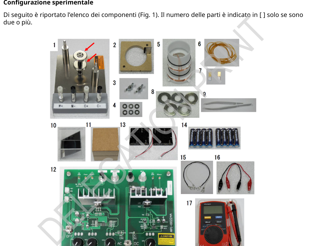
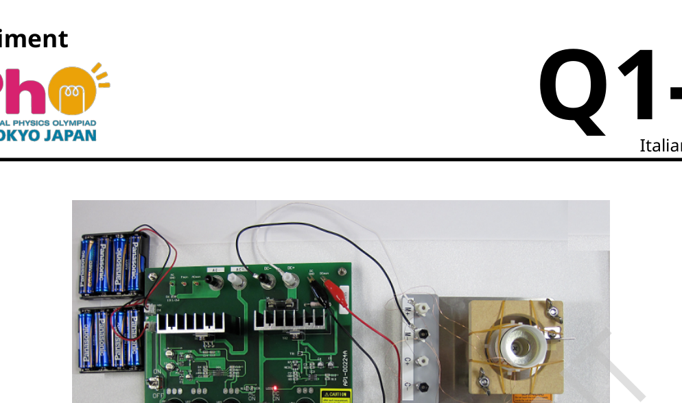
Experiment Q1-1 Italiano (Italy) Misura di massa (10 punti) In questo problema sperimentale si cerca di fare una misura di massa. Misuriamo inoltre la massa utilizzando le caratteristiche di risonanza dell’oscillatore armonico. Configurazione sperimentale Di seguito è riportato l’elenco dei componenti (Fig. 1). Il numero delle parti è indicato in [ ] solo se sono due o più. Figura 1: L’apparato sperimentale.
- Base di montaggio: Nota: l’unità magnetica sulla base crea campi magnetici radiali uniformi garantiti indipendenti dall’altezza in prossimità del centro della coppia di magneti fino a mm in altezza.
- (Oscillatore) supporto
- Dado a farfalla [2]: Nota: rimuovere 2 e 3 da 1 nel materiale ricevuto per utilizzarlo.
- Spessori (rondelle) [6]
Experiment Q1-2 Italiano (Italy) 5. Oscillatore cilindrico 6. Elastici [6] 7. Segnalini [2] 8. Pesi [5] 9. Pinzette 10. Specchio 11. Blocco di rialzo 12. Alimentazione: È possibile attivare la modalità DC (corrente continua) o AC (corrente alternata). In modalità DC, funziona come sorgente di corrente costante. Ruotare la manopola ”DC Vol” per regolare la corrente. Il valore della corrente si ottiene dalla tensione tra ”DCmon” e ”DC GND” utilizzando il fattore di conversione 1.00 A/V. In modalità AC, funziona come sorgente di tensione con un’ampiezza fissa. Ruotare ”AC Vol” per regolare la tensione. La corrente alternata si ottiene dalla tensione tra ”ACmon” e ”AC GND” utilizzando il fattore di conversione 0.106 A/V. La frequenza (Freq.) può essere regolata utilizzando le manopole di regolazione ”Coarse” e ”Fine”. 13. Portabatterie [2] 14. Batterie [8] 15. Fili con collegato terminale a U [2] 16. Fili con terminale a coccodrillo [2] 17. Multimetro digitale (DMM): Ruotare la manopola per selezionare la modalità di misurazione appropriata, ”DCV”, ”ACV” e ”Hz”. Si noti che il valore visualizzato della tensione AC indica il valore quadratico medio (RMS), ossia il valore effettivo. Modellizzazione del sistema La Figura 2 rappresenta un modello semplificato dell’apparato sperimentale. Si tratta essenzialmente di un oscillatore forzato a massa su molla.
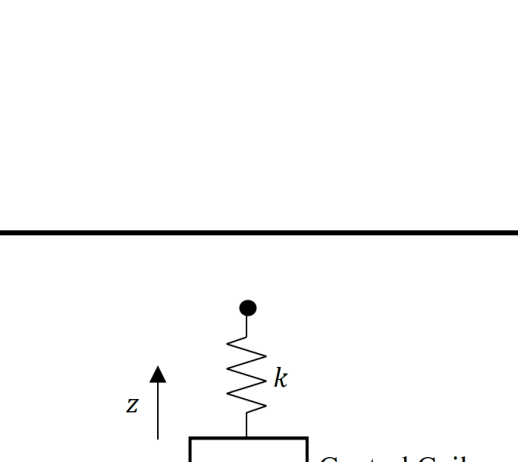
Experiment Q1-3 Italiano (Italy) Figura 2: Modello di oscillatore armonico. I parametri rilevanti sono: • M: massa dell’oscillatore (cilindrico) • m: massa di un pesetto • N: il numero di pesetti • g: accelerazione di gravità • k: costante elastica effettiva relativa al moto verticale • z: altezza (o spostamento) dell’oscillatore • ze: altezza dell’oscillatore alla quale si stabilisce l’equilibrio delle forze in assenza di forze elettromagnetiche e gravitazionali. • ): campo magnetico applicato alla bobina (di controllo) principale • ): lunghezza del filo conduttore della bobina (di controllo) principale • ): corrente che scorre attraverso la bobina (di controllo) principale • α: coefficiente positivo di resistenza aerodinamica L’equazione del moto è data da (M+ Nm)d2z dt2 = ) + BLI+ dt. (1) Installazione dell’oscillatore
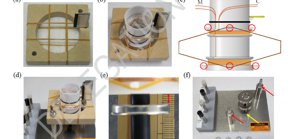
- Rimuovere il supporto dalla base di montaggio. Avvolgere quattro elastici intorno ad esso secondo uno schema a griglia (vedere la Fig. 3(a)).
- Inserire l’oscillatore cilindrico dal lato della bilancia nell’apertura quadrata in mezzo agli elastici incrociati. Posizionare i conduttori sull’altro lato della bilancia. (Fig. 3(b)).
- L’oscillatore è stato progettato per essere appeso al supporto con quattro elastici e otto piccoli ganci (cerchiati in rosso nella Fig. 3(c)). Se realizzato correttamente, un anello di elastici forma un rombo tronco con due ganci sopra e sotto il livello del supporto nella vista laterale. Nota: in questo esperimento, possiamo assumere che la forza effettiva dovuta agli elastici obbedisca alla legge di Hooke.
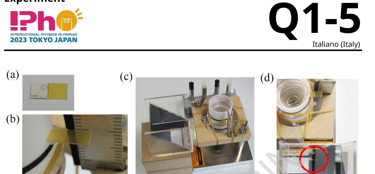
Experiment Q1-4 Italiano (Italy) 4. Fissare nuovamente il supporto al montante in diagonale con i due dadi a farfalla. La bilancia deve stare in piedi sopra, non a lato dei montanti (Fig. 3(d)). 5. Mettere l’oscillatore in posizione verticale. Il suo asse deve essere allineato verticalmente e coincidere con quello dell’unità magnetica. 6. La bobina principale dovrebbe trovarsi vicino al centro dei due magneti quando è a riposo, il che può essere confermato dalla distanza tra la superficie superiore del magnete inferiore e la superficie inferiore dell’oscillatore pari a 3-5 mm (Fig. 3(e) freccia rossa). Se è minore, inserire degli spessori tra i morsetti e il supporto (Fig. 3(f) freccia rossa). Se è maggiore, ruotare il montante del magnete per rimuoverlo e aggiungere lo spessore sotto il montante (Fig. 3(f) freccia gialla). 7. Esporre la superficie adesiva del nastro biadesivo sul segnalino (Fig. 4(a)). Incollare il segnalino sul piccolo ripiano fluttuante dell’oscillatore per misurare l’altezza (Fig. 4(b)). 8. Posizionare lo specchio sul blocco di rialzo (Fig. 4(c)). Assicurare una visione chiara del segnalino dall’alto attraverso lo specchio (Fig. 4(d) cerchio rosso). Figura 3: Installazione dell’oscillatore.
Experiment Q1-5 Italiano (Italy) Figura 4: Installazione del segnalino e dello specchio. Cablaggio
- Individuare e tirare delicatamente la coppia di fili corretta che conduce alle bobine principali (M) e di controllo (C) (Fig. 3(c)) dall’interno dell’oscillatore (Fig. 3(b)). Controllare se lo smalto è stato tolto dalle estremità allentate.
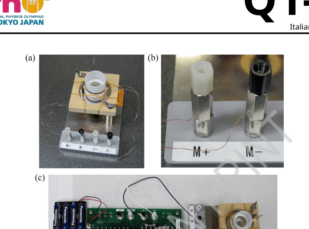
- Allentare la vite sui morsetti M+ e M- per lasciare degli spazi vuoti. Utilizzare gli spazi inferiori per il cablaggio (Fig. 5(a), (b)). Il controllo della polarità verrà spiegato dopo.
- Collegare allo stesso modo i morsetti etichettati C+ e C-. (Entrambe le polarità sono accettabili).
- Posizionare le batterie negli appositi supporti e fissare i collegamenti con l’alimentatore (CN1, CN2) (Fig. 5(c)).
- Collegare i morsetti M+ e M- all’uscita DC (DC+ e DC-) dell’alimentatore utilizzando i fili dei terminali a U.
- Selezionare corrente continua (DC) e accendere l’alimentatore.
- Ruotare la manopola ”DC Vol.” per regolare la corrente. Verificare se l’oscillatore si sposta verso l’alto di 2mm o di più. Se si muove verso il basso, scambiare i fili per invertire la polarità e riprovare. Attenzione: Parti calde. Attenzione alle bobine e ai magneti. Al termine di ogni fase, abbassare l’uscita DC al minimo.
Experiment Q1-6 Italiano (Italy) Figura 5: (a), (b) I morsetti cablati, (c) L’intero impianto cablato, compresi alimentazione e batterie. Prova dell’oscillatore
- Collegare i morsetti M+ e M- all’uscita AC (AC+ e AC-) con i fili con i terminali a U.
- Selezionare corrente alternata (AC) e accendere l’alimentatore.
- Ruotare la manopola ”AC Vol.” in senso orario partendo dal minimo fino a un quarto di giro. Sintonizzare la frequenza con la manopola ”Coarse” per avviare l’oscillazione.
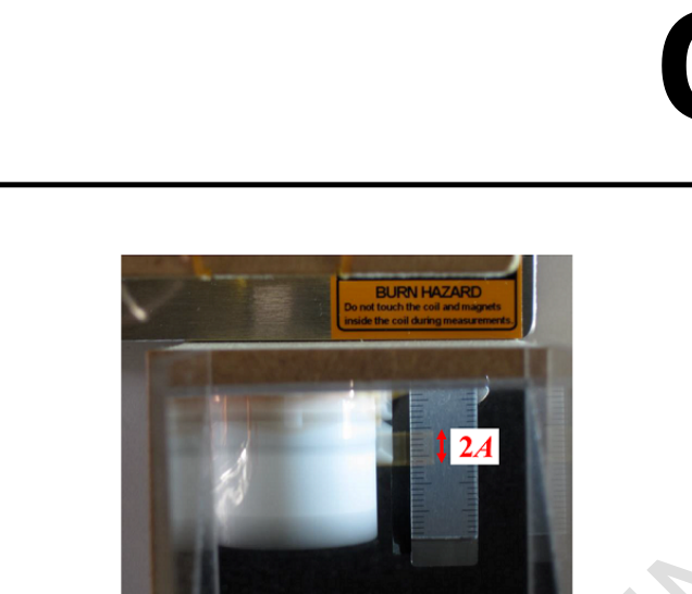
- Regolare la tensione e la frequenza di uscita AC per ottenere un’oscillazione di ampiezza A= 3 mm circa (Fig. 6). Se l’oscillazione è instabile, regolare le impostazioni dell’oscillatore in modo appropriato.
- Scollegare M+ e M- e collegare i morsetti C+ e C- all’uscita AC.
- Accendere l’alimentatore per far partire di nuovo l’oscillazione.
Experiment Q1-7 Italiano (Italy) Figura 6: comportamento dell’oscillazione visto attraverso lo specchio. Parte A. Legge di Hooke e forze elettromagnetiche (2.4 punti) A.1 Disegnare nel foglio risposte le linee di campo magnetico create dai due magneti identici a forma di disco quando i poli N sono rivolti l’uno verso l’altro. 0.4 pt A.2 Collegare i morsetti M+ e M- all’uscita DC. Accoppiare il DMM con i terminali per la lettura della corrente C utilizzando i fili a coccodrillo (Fig. 7). Leggere l’altezza dell’oscillatore a corrente continua nulla senza pesi addizionali, ossia, N= 0. Scrivi il dato nella Tabella A.2. Mettere un peso (N= 1) su un ripiano circolare che sporge dalla parete interna del cilindro e registrare l’altezza za cui l’oscillatore si ferma. Qual è il valore della corrente continua Iche bisogna far scorre nella bobina principale per riportare l’oscillatore al punto
p.1 — Apparato sperimentale: componenti numerati
p.3 — Modello di oscillatore armonico
p.4 — Installazione dell’oscillatore, pannelli a-e
p.5 — Installazione segnalino e specchio, pannelli a-d
p.6 — Morsetti e impianto cablato completo
p.7 — Oscillatore visto attraverso lo specchio
p.8 — DMM collegato e oscillatore con peso
Topic: Oscillations & Waves, Magnetism, Newtonian Mechanics Metodi: Simple Harmonic Motion Analysis, Hooke’s Law, Lorentz Force Analysis, Free-Body Diagram Competenze: Experimental Data Analysis, Diagrammatic Reasoning, Mathematical Modeling Objects: Spring, Magnet, Coil, Mirror, Battery Fonte: Testo (PDF) — p.1 Soluzione: Soluzioni (PDF)
Experiments Q1-1 Italian (Italy) Mass measurement (10 points) In this experimental problem we are trying to make a mass measurement. We also measure the mass using the resonance characteristics of the harmonic oscillator. The test shall be carried out in accordance with the following conditions: The following is a list of the components (Fig. 1). The number of parts is indicated in [ ] only if they are Two or more. Figure 1: The experimental apparatus.
- The following is the list of the following: Note: the magnetic unit on the basis creates independent guaranteed uniform radial magnetic fields from the height near the centre of the magnetic torque to mm in height.
- (Obscillator) support
- Butterflyfish [2]: Note: Remove 2 and 3 from 1 in the material received for use.
- Other, of a thickness of not more than 10 mm
Experiments Q1-2 Italian (Italy) 5. Other, of a kind used for the manufacture of goods of heading 8106 6. Other, of a kind used for the manufacture of goods 7. Signals [2] 8. Weights [5] 9. Other, of a thickness of not more than 0,01 mm 10. Mirror 11. The amount of the loan shall be calculated as follows: 12. Food: The DC (continuous current) or AC (alternating current) mode can be activated. In DC mode, it works as a constant current source. Rotate the crankcase DC Vol for I’m going to adjust the current. The current value is obtained from the voltage between DCmon and DC GND using the conversion factor 1.00 A/V. In AC mode, it operates as a fixed-amplitude voltage source. Rotate AC Vol to adjust the voltage. The alternating current is obtained from the voltage between ACmon and AC GND using The conversion factor is 0,106 A/V. The frequency (Freq.) can be adjusted using the Coarse and Fine controls. 13. Other, of a kind used for the manufacture of electrical equipment 14. Batteries [8] 15. Wire with terminal connection to U [2] 16. Wire with crocodile terminal [2] 17. The following information shall be provided: Rotate the handle to select the appropriate measurement mode, DCV, ACV and Hz. Note that the displayed value of the AC voltage indicates the mean square value (RMS), i.e. the the actual value. Modelling of the system Figure 2 is a simplified model of the experimental apparatus. It is essentially a matter of a mass-force oscillator on the spring.
Experiments Q1-3 Italian (Italy) Figure 2: Model of harmonic oscillator. The relevant parameters are: • M: mass of the oscillator (cylinder) • m: mass of one peset • N: number of pesetas • g: acceleration by gravity • k: effective elastic constant relative to the vertical motion • z: height (or displacement) of the oscillator • Ze: height of the oscillator at which the balance of forces is established in the absence of electromagnetic and gravitational forces. • : magnetic field applied to the main (control) coil • : length of the main (control) coil conductive wire • : current flowing through the main (control) coil • α: positive coefficient of aerodynamic resistance The equation of the motion is given by (M+ Nm)d2z dt2 = ) + BLI+ dt. (1) Installation of the oscillator
- Remove the support from the assembly base. Wrap four rubbers around it second A grid pattern (see Figure 1. 3(a)).
- Insert the cylindrical oscillator from the side of the scale into the square opening in the middle of the tyres crossed. Position the drivers on the other side of the balance. (Fig. 3(b)).
- The oscillator is designed to be suspended from the support with four elastic straps and eight small hooks (circled in red in Fig. 3(c)). If made correctly, a rubber ring forms a rope a trunk with two hooks above and below the support level in the side view. Note: In this experiment, we can assume that the actual force due to the elastic is subject to Hooke’s law.
Experiments Q1-4 Italian (Italy) 4. Re-fix the support to the vertical side diagonally with the two butterfly dice. The balance sheet must be Standing on top, not on the side of the hills. 3(d)). 5. Set the oscillator in a vertical position. Its axis must be aligned vertically and coincide with that of the magnetic unit. 6. The main coil should be near the center of the two magnets when it is at rest, which can be confirmed by the distance between the upper surface of the magnet and the lower surface The maximum value of the oscillator is less than 3 to 5 mm (Fig. 3 (e) red arrow). If it is smaller, insert thicknesses The main features of the device are the use of the brushes and the support (Fig. 3 (f) red arrow). If it is larger, rotate the magnetic surge The weight of the material is not less than 0,5% of the weight of the material. 3 (f) yellow arrow). 7. Exposing the adhesive surface of the bi-adhesive tape on the indicator (Fig. 4(a)). Pasting the sign on the The small floating plane of the oscillator to measure the height (Fig. 4(b)). 8. Position the mirror on the upper block (Fig. 4(c)). Ensure clear vision of the sign From above through the mirror (Fig. 4 (d) red circle). Figure 3: Installation of the oscillator.
Experiments Q1-5 Italian (Italy) Figure 4: Installation of the sign and mirror. Other, of a kind used for the manufacture of goods
- Detect and gently pull the correct wire pair leading to the main coil (M) and The Commission has already adopted a number of proposals for a new programme. 3(c)) from the inside of the oscillator (Fig. 3(b)). Check if the enamel has been removed from loose ends.
- Loosen the screws on the M+ and M- wrists to leave empty spaces. Use the lower spaces for the The Commission has already adopted a proposal for a directive on the approximation of the laws of the Member States relating to the use of electricity. 5(a), (b)). The polarity control will be explained later.
- The C+ and C-marked knobs shall be connected in the same way. (Both polarities are acceptable).
- Place the batteries in the appropriate supports and connect them to the power supply (CN1, CN2) (Fig. 5(c)).
- Connecting the M+ and M-DC-output (DC+ and DC-) winding of the power supply using the terminal wires a U.
- Select direct current (DC) and turn on the power supply.
- Rotate the DC Vol. handle to adjust the current. Check whether the oscillator is moving towards 2 mm or more in height. If you move down, swap the wires to reverse the polarity and try again. Warm parts. Watch out for the coils and the magnets. At the end of each stage, lower the The DC output is minimal.
Experiments Q1-6 Italian (Italy) Figure 5: (a), (b) Wired seals, (c) The whole wired system, including power and The batteries. Test of the oscillator
- Connect the M+ and M-output AC (AC+ and AC-) wires to the U-terminals.
- Select alternating current (AC) and turn on the power supply.
- Rotate the AC Vol. clockwise from the minimum to a quarter turn. Tune the frequency with the Coarse handle to start the oscillation.
- Adjust the AC output voltage and frequency to achieve an A= amplitude oscillation The size of the sample is approximately 3 mm (Fig. 6). If the oscillation is unstable, adjust the oscillator settings so that the oscillator is not The Commission has not yet taken a decision.
- Connect M+ and M- and connect the C+ and C-cranks to the AC output.
- Turn on the power supply to restart the oscillation.
Experiments Q1-7 Italian (Italy) Figure 6: Oscillation behaviour seen through the mirror. Part A. Hooke’s laws and electromagnetic forces (2.4 points) A.1 Draw the magnetic field lines created by the two identical disk-shaped magnets when the N poles are facing each other. 0.4 pt A.2 Connect the M+ and M-output DC brackets. Couple the DMM with the terminals for The current C reading using the crocodile wires (Fig. 7). Reading the height of the DC oscillator is nothing without additional weights, That is, N=0. Enter the data in Table A.2. Put a weight (N= 1) on a circular plane protruding from the inner wall The cylinder shall be kept on the same level as the cylinder and the height at which the oscillator stops. What is the value of the DC current that must be drawn into the coil main to bring the oscillator back to the point
p.1 — Apparato sperimentale: componenti numerati
p.3 — Modello di oscillatore armonico
p.4 — Installazione dell’oscillatore, pannelli a-e
**p.5 ** Signal and mirror installation, a-d panels
**p.6 ** Full cable-stayed plugs and fittings
**p.7 ** Oscillator seen through the mirror
p.8 DMM connected and oscillator by weight
Topic: Oscillations & Waves, Magnetism, Newtonian Mechanics Metodi: Simple Harmonic Motion Analysis, Hooke’s Law, Lorentz Force Analysis, Free-Body Diagram Competenze: Experimental Data Analysis, Diagrammatic Reasoning, Mathematical Modeling Objects: Spring, Magnet, Coil, Mirror, Battery Fonte: Testo (PDF) — p.1 Soluzione: Soluzioni (PDF)