Experiment Q2-1 Italiano (Italy) La legge di Wiedemann-Franz Nei metalli, il calore è trasmesso prevalentemente dagli elettroni. Per questa ragione, la conducibilità termica e la conduttività elettrica sono collegate. La relazione che lega queste due grandezze è nota come legge di Wiedemann-Franz. In questo esperimento, l’obiettivo è misurare le proprietà termiche ed elettriche di diversi materiali con una accuratezza ragionevolmente alta. Nella Parte A misureremo la conduttività elettrica del rame, dell’ottone e dell’alluminio. Nella Parte B misureremo la conducibilità termica del rame. Nella Parte C misureremo il calore specifico del rame. Nella Parte D misureremo la conducibilità termica dell’ottone e dell’alluminio. Infine, nella Parte E, verificheremo che i nostri risultati sono in accordo con la legge generale che lega queste quantità nei metalli che abbiamo considerato.
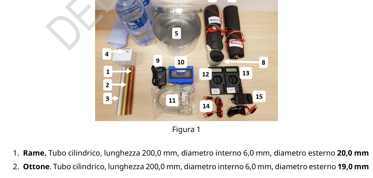
In questo esperimento non è richiesto svolgere alcun calcolo degli errori. Si noti che nelle parti B e D c’è una fase che richiede un’attesa di 15 minuti. Si pianifichino tutte le procedure tenendone conto. Norme di sicurezza Non connettere alcun cavo o strumento non autorizzato direttamente alla presa di rete 220 V/25 A. È permesso connettere alla presa di rete solo gli alimentatori forniti, senza che questi possano essere modificati. Materiale Figura 1
- Rame. Tubo cilindrico, lunghezza 200,0 mm, diametro interno 6,0 mm, diametro esterno 20,0 mm
- Ottone. Tubo cilindrico, lunghezza 200,0 mm, diametro interno 6,0 mm, diametro esterno 19,0 mm
Experiment Q2-2 Italiano (Italy) 3. Alluminio. Tubo cilindrico, lunghezza 200,0 mm, diametro interno 6,0 mm, diametro esterno 20,0 mm 4. Un piccolo magnete permanente di massa 1,2 g. 5. Un contenitore per l’acqua (si tratta di un pentolino utilizzato per la preparazione di un piatto locale chiamato ”Jachun”, un dolce israeliano). Il coperchio della pentola è dotato di uno scambiatore di calore nella parte interna e di una vite nella parte esterna. Vengono forniti 4 litri di acqua naturale (due bottiglie da 2 litri) . 6. Barretta #1. Barretta di rame, di diametro 20,0 mm, dotata di sensori di temperatura collegati a un cavo e di un riscaldatore collegato ai cavi rossi (Figura 2.a). I cavi rossi devono essere connessi all’alimentatore DC (punto 15 qui sotto) tramite un circuito. La barretta è ricoperta di un materiale schiumoso nero e isolante. 7. Barretta #2. Barretta di materiale composito, di diametro 20,0 mm, dotata di sensori di temperatura collegati a un cavo e di un riscaldatore collegato ai fili rossi (Figura 2.b). I cavi rossi devono essere connessi all’alimentatore DC (punto 15 qui sotto) tramite un circuito. La barretta è ricoperta di un materiale schiumoso nero e isolante. 8. Tappo di chiusura termicamente isolante 9. Alimentatore 12 V in corrente continua (DC), per l’interfaccia digitale 10. Interfaccia digitale. Questa interfaccia mostra i valori registrati da 8 sensori di temperatura (termometri) simultaneamente e il tempo, si vedano le istruzioni nel seguito. Questo apparecchio viene usato anche come cronometro. 11. Cavi per collegare i sensori di temperatura della barretta all’interfaccia digitale 12. Voltmetro. Il selettore del voltmetro deve essere impostato a 20 V DC (corrente continua). Vedi figura 3. 13. Amperometro. L’amperometro deve essere impostato a 10 ampere DC (corrente continua). Vedi figura 3. 14. Fili elettrici 15. Alimentatore 9 V DC per il riscaldatore con connettori a banana. ATTENZIONE
- È permesso connettere alla presa di corrente solo gli alimentatori forniti e dotati di spina standard AC. E’ severamente vietato collegare cavi isolati o altri apparecchi alla presa di corrente e si possono causare gravi danni a oggetti e persone.
- Non immergere le barrette nell’acqua.
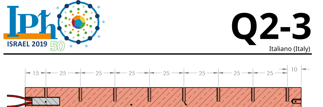
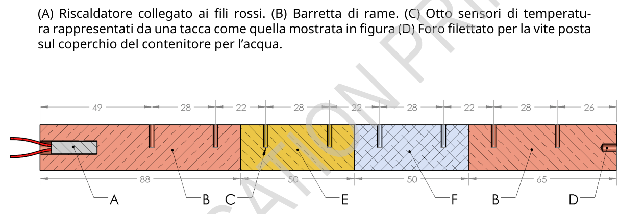
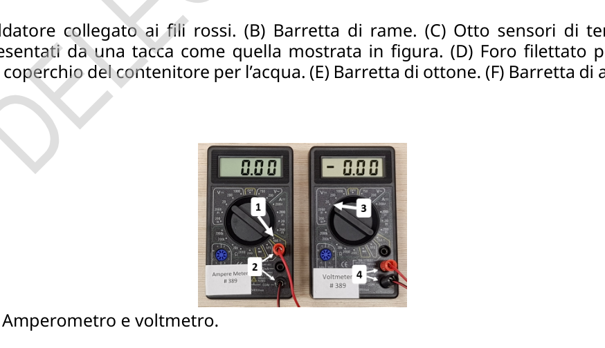
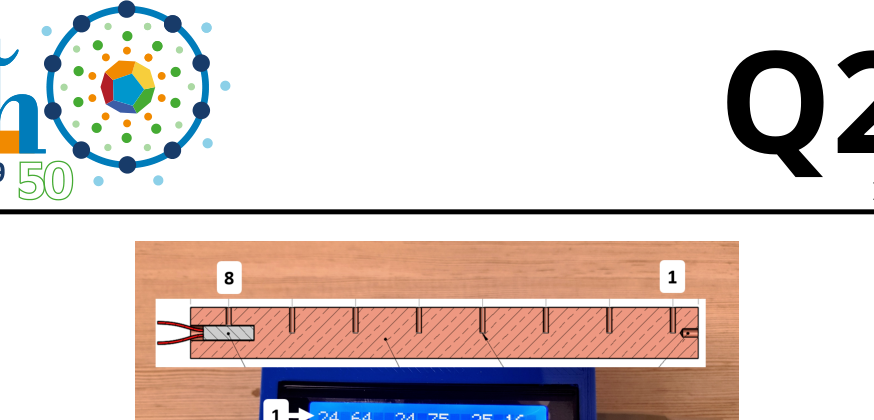
Experiment Q2-3 Italiano (Italy) Figura 2.a .Schema della Barretta #1. Le distanze sono fornite in mm con la precisione di 0,1 mm. (A) Riscaldatore collegato ai fili rossi. (B) Barretta di rame. (C) Otto sensori di temperatura rappresentati da una tacca come quella mostrata in figura (D) Foro filettato per la vite posta sul coperchio del contenitore per l’acqua. Figura 2.b. Schema della Barretta 2. Le distanze sono fornite in mm con la precisione di 0,1 mm. (A) Riscaldatore collegato ai fili rossi. (B) Barretta di rame. (C) Otto sensori di temperatura rappresentati da una tacca come quella mostrata in figura. (D) Foro filettato per la vite posta sul coperchio del contenitore per l’acqua. (E) Barretta di ottone. (F) Barretta di alluminio. Figura 3. Amperometro e voltmetro. (1) Posizione del selettore su 10 A come per l’esperimento. (2) Terminali d’ingresso dell’amperometro. (3) Posizione del selettore su 20 V come per l’esperimento. (4) Terminali di ingresso per il voltmetro.
Experiment Q2-4 Italiano (Italy) Utilizzo dell’interfaccia digitale Collegare l’interfaccia al suo alimentatore da 12 V DC. L’interfaccia digitale ha 2 modalità di funzionamento: cronometro e termometro. Quando i cavi dei sensori sono collegati all’interfaccia, quest’ultima passerà automaticamente alla modalità termometro. Quando i cavi sono disconnessi, l’interfaccia passa automaticamente alla modalità cronometro e lo schermo mostra la dicitura ”Timer mode”. In modalità termometro: • Mantenere premuto per 3 secondi il pulsante rosso per azzerare il cronometro. • Premere brevemente il pulsante rosso per bloccare il valore mostrato sul display (l’interfaccia continua a misurare il tempo trascorso anche se non lo mostra). • Premere nuovamente il pulsante rosso per riprendere la visualizzazione della temperatura dal vivo e del tempo In modalità cronometro: • Premere il pulsante rosso per far partire il cronometro. • Premere nuovamente il pulsante rosso per fermare il cronometro. • Premere un’altra volta il pulsante rosso per azzerare il cronometro. L’interfaccia digitale deve essere calibrata per ciascuna barretta prima del suo primo utilizzo. I termometri usati nell’esperimento non sono tutti esattamente uguali. Di conseguenza, quando la barretta è in equilibrio termico, si vuole calibrare i termometri in modo che tutti segnino la stessa temperatura. Per far sì che ciò accada, collegare alla barretta un capo del cavo per i sensori di temperatura; premere e mantenere premuto il pulsante rosso mentre si connette l’altro capo del cavo all’interfaccia. La disconnessione dell’interfaccia dall’alimentazione o dai sensori di temperatura non resetta la calibrazione. ATTENZIONE: effettuare la calibrazione prima di connettere la barretta al contenitore per l’acqua o il riscaldatore interno all’alimentazione. Questo garantisce che la temperatura della barretta sia uniforme durante la calibrazione. In caso di problemi con l’interfaccia digitale, potrebbe essere utile disconnetterla e riconnetterla all’alimentazione. L’interfaccia non perde la calibrazione nel processo di disconnessione e riconnessione.
Experiment Q2-5 Italiano (Italy) Figura 4. Interfaccia digitale (A) Cavo per l’alimentatore a 12 V DC. (B) Pulsante rosso multifunzione. (C) Cavo per i sensori di temperatura. (1-8) Lettura in gradi Celsius dei valori registrati dagli 8 sensori di temperatura, ordinati per righe. Parte A: Conduttività elettrica di rame, alluminio e ottone (1.5 punti) Premesse teoriche Quando un magnete permanente cade dentro un tubo cilindrico conduttore, su di esso agisce una forza dissipativa dovuta alle correnti parassite indotte. Di conseguenza, il magnete raggiunge una velocità limite. In questa situazione la velocità limite può essere espressa come: vlimite= 8πmga2 μ2 0(πr2mM)2σwf( da) . (1) dove mè la massa del magnete, σè la conduttività elettrica del materiale del tubo, aè il raggio interno del tubo, rme dsono rispettivamente il raggio e l’altezza del magnete, Mè la magnetizzazione del magnete, wè lo spessore della parete del tubo e f( da) è un fattore di scala. In questo caso, , d= f(2) . Di conseguenza, il tempo impiegato dal magnete per cadere attra
p.1 — Foto dei materiali e barrette metalliche
p.3 — Schema della Barretta numero uno
p.3 — Schema della Barretta numero due
p.3 — Amperometro e voltmetro
p.5 — Interfaccia digitale
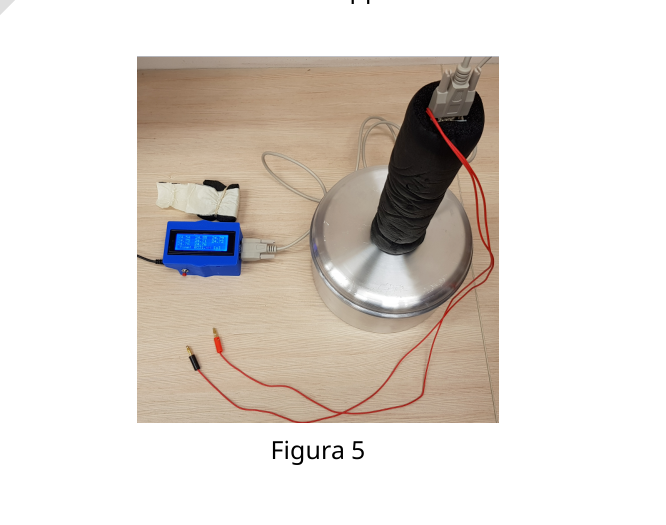
p.6 — Apparato barretta e contenitore
Topic: Thermodynamics, Electromagnetic Induction, Circuits Metodi: Faraday’s Law of Induction, Experimental Data Analysis, Graph Linearization Competenze: Experimental Data Analysis, Measurement & Instrumentation, Graph Linearization Objects: Tube, Magnet, Container Fonte: Testo (PDF) — p.1 Soluzione: Soluzioni (PDF)
Experiments Q2-1 Italian (Italy) The Wiedemann-Franz law In metals, heat is transmitted mainly by electrons. For this reason, the conductivity of the thermal and electrical conductivity are connected. The relationship between these two greatness is well known. The law of Wiedemann-Franz. In this experiment, the aim is to measure the thermal and electrical properties of different materials with a reasonably high accuracy. In Part A we measure the electrical conductivity of copper, brass and aluminium. In Part B we will measure the thermal conductivity of copper. In Part C we measure the specific heat of copper. In Part D we will measure the thermal conductivity of brass and aluminium. Finally, in Part E, we will check that our results are in accordance with the general law which binds these amounts to the metals we’ve considered.
In this experiment, no error calculation is required. It is noted that in Parts B and D there is a phase requiring a 15 minute wait. All the The Commission shall take into account the procedures. The following information shall be provided: Do not connect any unauthorised cable or instrument directly to the 220 V/25 A network outlet. È Only supplied power supplies are allowed to be connected to the power supply, without the power supplies being the amendments. Other materials The following is the list of the following:
- The branch. Cylindrical tube, length 200,0 mm, inner diameter 6,0 mm, outer diameter 20,0 mm
- I’m going to get it. Cylindrical tube, length 200,0 mm, inner diameter 6,0 mm, outer diameter 19,0 mm
Experiments Q2-2 Italian (Italy) 3. - It’s aluminum. Cylindrical tube, length 200,0 mm, inner diameter 6,0 mm, outer diameter 20,0 mm 4. A small permanent magnet with a mass of 1.2 g. 5. A water container (a pencil used for preparing a local dish) called Jachun, an Israeli sweet). The pot lid shall be equipped with a heat inside and a screw outside. 4 litres of natural water are supplied (two two-litre bottles) 6. Bar #1. Copper rod, of a diameter of 20,0 mm, with temperature sensors connected to a cable and a heater connected to the red cables (Figure 2.a). The red cables must be connected the DC power supply (point 15 below) by means of a circuit. The bar is covered with a material It’s foamy black and insulating. 7. Barrette number two. Other, of a width of not more than 20 mm, of a width of not more than 30 mm connected to a cable and a heater connected to red wires (Figure 2.b). The red cables must be connected to the DC power supply (point 15 below) by means of a circuit. The bar is covered with a black foaming material and insulating material. 8. Heat-insulating closure cap 9. 12 V DC power supply for the digital interface 10. It’s a digital interface. This interface shows the values recorded by 8 temperature sensors (thermometers) simultaneously and the time, see the instructions below. This device comes It’s also used as a timekeeper. 11. Cables for connecting the temperature sensors of the bar to the digital interface 12. I’m going to go back. The voltmeter selector shall be set to 20 V DC (continuous current). See ? The following table shows the results of the study: 13. I’m going to get a meter. The amperometer shall be set to 10 DC (continuous current) amperes. See ? The following table shows the results of the study: 14. Electrical wires 15. 9 V DC power for the heater with banana connectors. Attention
- Only supplies supplied with standard AC spindle are permitted to be connected to the power supply. It is strictly prohibited to connect insulated cables or other appliances to the power supply and may cause serious damage to objects and people.
- Do not dip the bars in the water.
Experiments Q2-3 Italian (Italy) Figure 2.a. Schema of the Barret #1. The distances shall be provided in mm with an accuracy of 0,1 mm. (A) Heater connected to red wires. (B) Bar of copper. (C) Eight temperature sensors represented by a header such as that shown in Figure (D) Threaded for the mail screw on the lid of the water container. The following table shows the following: Schedule of Barrett 2. The distances shall be provided in mm with an accuracy of 0,1 mm. (A) Heater connected to red wires. (B) Bar of copper. (C) Eight temperature sensors represented by a height like that shown in the figure. (D) Filed for life placed on the lid of the water container. (E) Brass rod. (F) Aluminum rod. Figure 3 is shown. Amper and voltmeter. (1) Position of the selector on 10A as for the experiment. (2) Entrance terminals of the amperometer. (3) Position of the selector at 20 V as for the experiment. (4) Entry terminals for The voltmeter.
Experiments Q2-4 Italian (Italy) Use of the digital interface Connect the interface to its 12 V DC power supply. The digital interface has two modes of operation: a timer and a thermometer. When the sensor cables are connected to the interface, the interface will automatically switch to thermometer mode. When the cables are disconnected, the interface automatically switches to timer mode and the screen shows the expression Timer mode. In thermometer mode: • Hold the red button for 3 seconds to turn the timer to zero. • Press the red button briefly to lock the value shown on the display (the interface continues to measure the time spent even if it does not show it). • Press the red button again to resume the live temperature display and time In time-switched mode: • Press the red button to start the timer. • Press the red button again to stop the timer. • Press the red button again to turn the timer to zero. The digital interface must be calibrated for each bar before its first use. The thermometers used in the experiment are not all exactly the same. Consequently, when the bar is In thermal equilibrium, you want to calibrate the thermometers so that they all mark the same temperature. For To make this happen, connect one end of the cable for temperature sensors to the bar; press and hold the red button while the other end of the cable is connected to the interface. Disconnection The interface from the power supply or temperature sensors does not re-calibrate. ATTENTION: calibrate before connecting the bar to the water or water container Heating system for internal supply. This ensures that the barrel temperature is uniform. during the calibration. In case of problems with the digital interface, disconnecting it and reconnecting it to the power supply may be useful. The interface does not lose calibration in the disconnection and reconnection process.
Experiments Q2-5 Italian (Italy) Figure 4 is shown. The following information is provided: (A) 12 V DC power supply cable. (B) Multifunctional red pulse. (C) Cable for the temperature sensors. (1-8) Celsius reading of the values recorded by the 8 sensors of the temperature, sorted by row. Part A: Electrical conductivity of copper, aluminium and brass (1.5 points) Theoretical premises When a permanent magnet falls into a conductive cylindrical tube, a force acts on it The Commission has already established that the Commission is not in a position to adopt a decision on the application of the provisions of this Regulation. As a result, the magnet reaches a speed of The limit. In this situation the speed limit can be expressed as: I’m not sure. The following table shows the results of the evaluation: μ2 The following table shows the results of the evaluation: . (1) where the mass of the magnet is σ is the electrical conductivity of the tube material, i.e. the inner radius of the tube. The magnetic field and height of the magnet, respectively, where the thickness of the tube wall and f(d) is a scale factor. In this case, , d= f(2) . As a result, the time taken by the magnet to fall attract
**p.1 ** Photographs of metallic materials and bars
The following is the list of the types of the type of the vehicle:
The following table shows the number of the number of the number of the bar.
The following table shows the results of the calculations:
The following information is provided by the Commission:
**p.6 ** Barrel and container apparatus
Topic: Thermodynamics, Electromagnetic Induction, Circuits Metodi: Faraday’s Law of Induction, Experimental Data Analysis, Graph Linearization Competenze: Experimental Data Analysis, Measurement & Instrumentation, Graph Linearization Objects: Tube, Magnet, Container Fonte: Testo (PDF) — p.1 Soluzione: Soluzioni (PDF)