41-esima Olimpiade Internazionale della Fisica — Prova sperimentale — Croazia, 21 Luglio 2010
Ci sono due problemi sperimentali. L’apparato sperimentale sul tuo tavolo serve per entrambi. Hai 5 ore di tempo per completare entrambi i problemi.
Problema sperimentale 2: Forze tra magneti, concetti di stabilità e simmetria
Introduzione
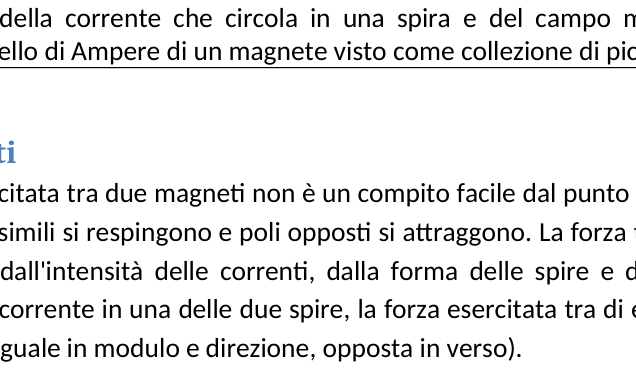
Una corrente elettrica che gira attorno ad una spira di area crea un momento magnetico di intensità [vedi Fig. 1(a)]. Un magnete permanente può essere schematizzato come una collezione di piccoli momenti magnetici di ferro (Fe), ciascuno dei quali è analogo al momento magnetico generato da una spira percorsa da corrente. Questo modello (il modello di Ampere) di un magnete è illustrato in Fig. 1(b). Il momento magnetico totale è la somma di tutti i piccoli momenti magnetici ed è diretto dal polo sud al polo nord.
(Fig. 1: (a) Schizzo della corrente che circola in una spira e del campo magnetico prodotto di conseguenza. (b) Modello di Ampere di un magnete visto come collezione di piccole spire.)
Forze tra magneti
Calcolare la forza esercitata tra due magneti non è un compito facile dal punto di vista teorico, anche se è risaputo che poli simili si respingono e poli opposti si attraggono. La forza tra due spire percorse da corrente dipende dall’intensità delle correnti, dalla forma delle spire e dalla loro distanza. Se invertiamo il flusso di corrente in una delle due spire, la forza esercitata tra di esse diventa l’opposto della forza originale (uguale in modulo e direzione, opposta in verso).
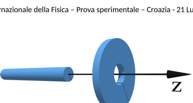
In questo problema cercherai di determinare sperimentalmente la forza esercitata tra due magneti, in particolare tra un anello magnetico e un cilindretto magnetico. Considera solo il caso in cui i due assi di simmetria dei magneti coincidono (vedi Fig. 2). Il cilindretto magnetico si può muovere lungo l’asse da sinistra attraversando l’anello e poi proseguendo verso destra (vedi Fig. 2). Tra le altre richieste, ti verrà anche chiesto di misurare sperimentalmente la forza esercitata tra i magneti in funzione di . L’origine corrisponde al punto in cui i centri dei magneti coincidono.
(Fig. 2: Il cilindretto magnete e l’anello magnete sono allineati. La forza esercitata dall’uno sull’altro varia facendo muovere il cilindretto lungo l’asse .)
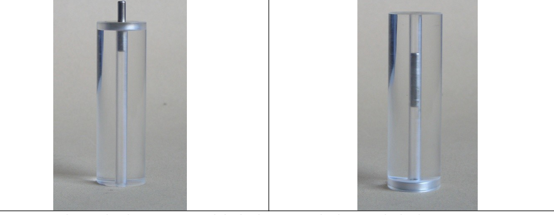
Per costringere il cilindretto magnete a muoversi lungo il suo asse di simmetria (l’asse ), l’anello magnete è saldamente incollato a un cilindro trasparente con un piccolo buco cilindrico lungo l’asse . Il cilindretto magnete in questo modo è costretto a muoversi lungo questo buco e quindi lungo l’asse (vedi Fig. 3). Entrambi i momenti magnetici sono diretti lungo l’asse ; inoltre il buco garantisce la stabilità del cilindretto magnete rispetto al movimento trasversale.
(Fig. 3: Foto di uno dei due magneti e del cilindro forato di plastica; il cilindretto magnete si muove lungo il buco del cilindro trasparente.)
Apparato sperimentale (problema 2)
Sul banco di lavoro sono a tua disposizione i seguenti strumenti (da utilizzare per il secondo problema):
- Una pressa (con un blocchetto di marmo); leggi le istruzioni specifiche se necessario.
- Una bilancia in grado di misurare masse fino a 5000 g in diverse unità di misura e con la funzione di TARA (leggi le istruzioni specifiche se necessario).
- Un cilindro forato di plastica trasparente con fissato ad uno dei suoi estremi un anello magnete.
- Un cilindretto magnete.
- Un sottile bastoncino di legno che può essere usato per tirare fuori il cilindretto magnete dal cilindro di plastica.
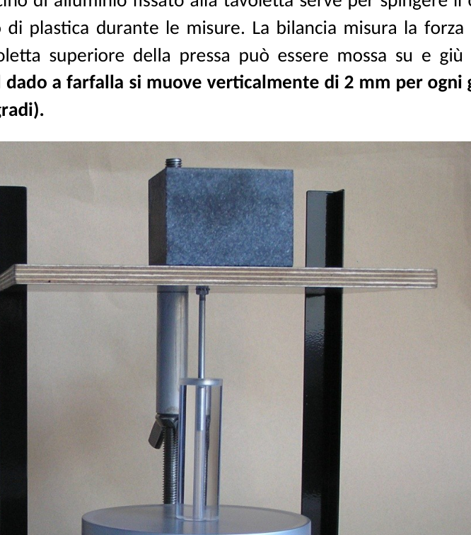
L’apparato deve essere usato come in Fig. 4 allo scopo di misurare la forza che agisce tra i due magneti. La tavoletta superiore della pressa deve essere girata sottosopra rispetto al problema precedente. Il bastoncino di alluminio fissato alla tavoletta serve per spingere il cilindretto magnete all’interno del cilindro di plastica durante le misure. La bilancia misura la forza (o meglio la massa equivalente). La tavoletta superiore della pressa può essere mossa su e giù tramite un dado a farfalla. Importante: il dado a farfalla si muove verticalmente di 2 mm per ogni giro completo (cioè quando ruota di 360 gradi).
(Fig. 4: Fotografia dell’apparato sperimentale e di come deve essere utilizzato per misurare la forza tra i due magneti.)
Richieste
-
Determina con osservazioni qualitative tutte le posizioni di equilibrio dei due magneti, assumendo che l’asse sia disposto in orizzontale come in Fig. 2, e disegnale (schizzale) sul foglio risposte. Per ogni posizione, determina se è stabile (S) o instabile (U) e indica il tipo di polo magnetico con un’ombreggiatura, come si vede nell’esempio di una posizione stabile riportata nel foglio risposte. Puoi rispondere a questa domanda utilizzando le tue mani e il bastoncino di legno. (2.5 punti)
-
Usando l’apparato sperimentale misura la forza tra i due magneti in funzione della coordinata . Per convenzione, scegli come positiva la direzione di che punta dentro al cilindro trasparente (ricorda: la forza è positiva se è diretta come la direzione positiva dell’asse di riferimento). Quando i due momenti magnetici sono paralleli, chiama la forza magnetica , mentre quando sono antiparalleli chiamala . Importante: va trascurata la massa del cilindretto magnetico (ovvero trascura la forza di gravità) e utilizza considerazioni di simmetria delle forze esercitate tra i magneti per determinare altre parti delle due curve. Scrivi chiaramente nel foglio risposte le simmetrie, che hai utilizzato, soddisfatte dalla forza magnetica. Riporta sul foglio risposte anche le misure che effettui e per ogni tabella schizza la configurazione dei magneti che hai studiato (segui l’esempio sul foglio risposte). (3.0 punti)
-
Usando le misure della richiesta 2, disegna in dettaglio sulla carta millimetrata un grafico di per . Disegna schematicamente anche la forma delle curve e (per valori sia positivi che negativi di ). Su ciascun grafico schematico evidenzia le posizioni di equilibrio stabile del sistema e schizza la corrispondente configurazione dei magneti (in maniera analoga alla richiesta 1). (4.0 punti)
-
Se non trascuriamo la massa del cilindretto magnete e l’asse è diretto in verticale, cerca qualitativamente se ci sono nuove posizioni di equilibrio stabile per il sistema. Se sì, disegnale sul foglio risposta in maniera analoga alla richiesta 1. (0.5 punti)
p.1 — Campo magnetico spira e cilindro magnetico
p.2 — Cilindro magnete con asse Z
p.2 — Foto magneti e cilindro forato
p.3 — Foto apparato misura forza tra magneti
Topic: Newtonian Mechanics Metodi: Physical Modeling, Free-Body Diagram Competenze: Measurement & Instrumentation, Physical Reasoning Objects: Magnet, Magnetic Dipole, Cylinder Fonte: Testo (PDF) — p.1 Soluzione: Soluzioni (PDF)
41st International Physics Olympiad Experimental Test Croatia, 21 July 2010
There are two experimental problems. The experimental device on your table is for both of us. You have five hours to complete both problems.
Experimental problem 2: Magnetic forces, concepts of stability and symmetry
♪ ♪ ♪ Introduction to the game ♪
An electric current that revolves around a spire of area creates a magnetic moment of intensity [see Fig. 1(a)]. A permanent magnet can be schematized as a collection of small magnetic moments of iron (Fe), each of which is analogous to the magnetic moment generated by a current-current spiral. This model (Ampere’s model) of a magnet is illustrated in Fig. 1(b). The total magnetic moment is the sum of all the small magnetic moments and it’s directed from the South Pole to the North Pole.
The Commission has also adopted a number of proposals for the implementation of the programme. 1: (a) A sketch of the current circulating in a spire and the magnetic field produced as a result. (b) Ampere model of a magnet seen as a collection of small spires.)*
Forces between magnets
Calculating the force exerted between two magnets is not an easy task from a theoretical standpoint, although it is known that similar poles repel and opposite poles attract. The force between two spires travelling by current depends on the intensity of the currents, the shape of the spires and their distance. If we reverse the current flow in one of the two spires, the force exerted between them becomes the opposite of the original force (equal in shape and direction, opposite in direction).
In this problem, you’ll try to experimentally determine the force exerted between two magnets, specifically between a magnetic ring and a magnetic cylinder. Consider only the case where the two axes of symmetry of the magnets coincide (see Fig. 2). The magnetic cylinder can be moved along the axis from the left through the ring and then continuing to the right (see Fig. 2). Among other requests, you will also be asked to experimentally measure the force exerted between magnets in a function of . The origin corresponds to the point where the centres of the magnets coincide.
The Commission has also adopted a number of proposals for the implementation of the programme. 2: The magnetic cylinder and the magnetic ring are aligned. The force exerted by each other varies by moving the cylinder along the axis .)*
To force the magnetic cylinder to move along its axis of symmetry (the axis), the magnetic ring is firmly attached to a transparent cylinder with a small cylindrical hole along the axis. The magnetic cylinder is thus forced to move along this hole and then along the axis (see Fig. 3). Both magnetic moments are directed along the axis; the hole also ensures the stability of the magnetic cylinder with respect to the transverse motion.
The Commission has also adopted a number of proposals for the implementation of the programme. 3: Photo of one of the two magnets and the plastic-holed cylinder; the magnetic cylinder moves along the transparent cylinder hole.)*
♪ experimental device (problem 2)
The following tools are available on the workbench (to be used for the second problem):
- A press (with a marble block); read the specific instructions if necessary.
- A scale capable of measuring masses up to 5000 g in different units of measurement and with the function of TARA (read the specific instructions if necessary).
- A transparent plastic perforated cylinder with a magnetic ring attached to one end.
- It’s a magnetic cylinder.
- A thin wooden stick that can be used to pull the magnetic cylinder out of the plastic cylinder.
The apparatus shall be used as shown in Fig. 4 to measure the force acting between the two magnets. The top of the press table must be turned upside down from the previous problem. The aluminium rod attached to the board is used to push the magnetic cylinder inside the plastic cylinder during measurements. The scale measures the force (or rather the equivalent mass). The top of the press table can be moved up and down by a butterfly dice. Important: the butterfly dice moves vertically by 2 mm for each complete turn (i.e. when rotating 360 degrees).
The Commission has also adopted a number of proposals for the implementation of the programme. 4: Photography of the experimental apparatus and how it should be used to measure the force between the two magnets.)*
# # Requests
-
Determine by qualitative observations all the equilibrium positions of the two magnets, assuming that the axis is horizontally arranged as in Fig. 2, and drawings on the answer sheet. For each position, determine whether it is stable (S) or unstable (U) and indicate the type of magnetic pole with a shading, as shown in the example of a stable position in the answer sheet. You can answer that question with your hands and your wooden stick. The amount of the aid shall be calculated on the basis of the following data:
-
Using the experimental apparatus, the force between the two magnets is measured at the coordinate. By convention, choose as positive the direction of pointing inward to the transparent cylinder (remember: the force is positive if directed as the positive direction of the reference axis). When the two magnetic moments are parallel, it calls the magnetic force , while when they are antiparallels it calls . Important: the mass of the magnetic cylinder must be ignored (i.e. the force of gravity must be ignored) and considerations of symmetry of the forces exerted between the magnets are used to determine other parts of the two curves. Write clearly on the sheet the symmetries you used, satisfied by the magnetic force. Also report on the answer sheet the measurements you make and for each table sketch the configuration of the magnets you studied (follow the example on the answer sheet). The following points shall be added:
-
Using the measurements of request 2, draw a detailed graph of for on millimeter paper. It also diagrammatically draws the shape of the curves and (for both positive and negative values of ). On each diagram, it shows the stable equilibrium positions of the system and sketches the corresponding configuration of the magnets (analogous to request 1). The following table shows the results of the calculation of the total cost of the vehicle:
-
If we do not neglect the mass of the magnetic cylinder and the axis is vertical, qualitatively look for new stable equilibrium positions for the system. If yes, draw the answer sheet in a manner similar to request 1. The following table shows the total number of points:
**p.1 ** Magnetic field of the spindle and magnetic cylinder
The following is the list of the main components of the engine:
p.2 Magnetic image and perforated cylinder
**p.3 ** Power measuring apparatus for imaging between magnets
Topic: Newtonian Mechanics Metodi: Physical Modeling, Free-Body Diagram Competenze: Measurement & Instrumentation, Physical Reasoning Objects: Magnet, Magnetic Dipole, Cylinder Fonte: Testo (PDF) — p.1 Soluzione: Soluzioni (PDF)