cada sullo schermo
- Accendi la sorgente laser e regola entrambi gli specchi in modo che il punto luminoso del laser cada sullo schermo.
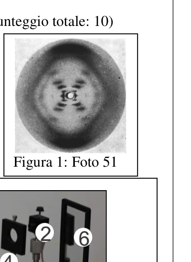
p.1 — Foto figura di diffrazione sullo schermo
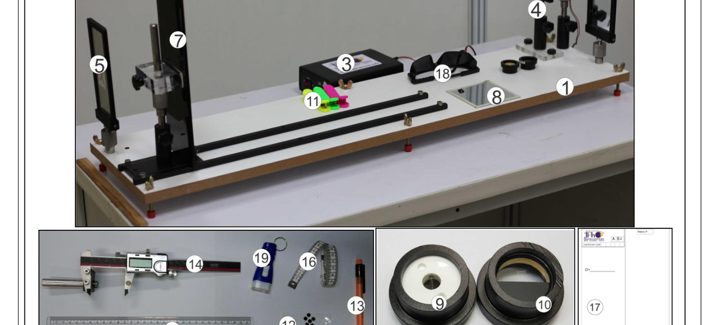
p.1 — Apparato sperimentale completo E-I
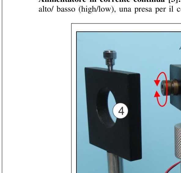
p.2 — Sorgente laser con portacampione
Topic: Geometric Optics Metodi: Physical Modeling Competenze: Measurement & Instrumentation Objects: Mirror, Screen Fonte: Testo (PDF) — p.4 Soluzione: Soluzioni (PDF)
fall on the screen
- Turn on the laser source and adjust both mirrors so that the laser bright spot It’s on the screen.
The following information is provided by the manufacturer:
The test shall be carried out in accordance with the following conditions:
The manufacturer shall provide the manufacturer with the following information:
Topic: Geometric Optics Metodi: Physical Modeling Competenze: Measurement & Instrumentation Objects: Mirror, Screen Fonte: Testo (PDF) — p.4 Soluzione: Soluzioni (PDF)
- Usa il righello graduato e regola il supporto del laser e gli specchi in modo che il fascio laser risulti parallelo alla tavola di legno.
Topic: Geometric Optics Metodi: Physical Modeling Competenze: Measurement & Instrumentation Objects: Mirror Fonte: Testo (PDF) — p.4 Soluzione: Soluzioni (PDF)
- Use the graduated reel and adjust the laser support and mirrors so that the laser beam It is parallel to the wood table.
Topic: Geometric Optics Metodi: Physical Modeling Competenze: Measurement & Instrumentation Objects: Mirror Fonte: Testo (PDF) — p.4 Soluzione: Soluzioni (PDF)
- Assicurati che il punto luminoso del laser cada vicino al centro dello schermo..
Topic: Geometric Optics Metodi: Physical Modeling Competenze: Measurement & Instrumentation Objects: Screen Fonte: Testo (PDF) — p.4 Soluzione: Soluzioni (PDF)
- Make sure the laser lighting falls near the center of the screen.
Topic: Geometric Optics Metodi: Physical Modeling Competenze: Measurement & Instrumentation Objects: Screen Fonte: Testo (PDF) — p.4 Soluzione: Soluzioni (PDF)
di diffrazione
- Spegni la sorgente laser. Fissa sullo schermo, con le mollette, un foglio di rilevamento delle figure di diffrazione.
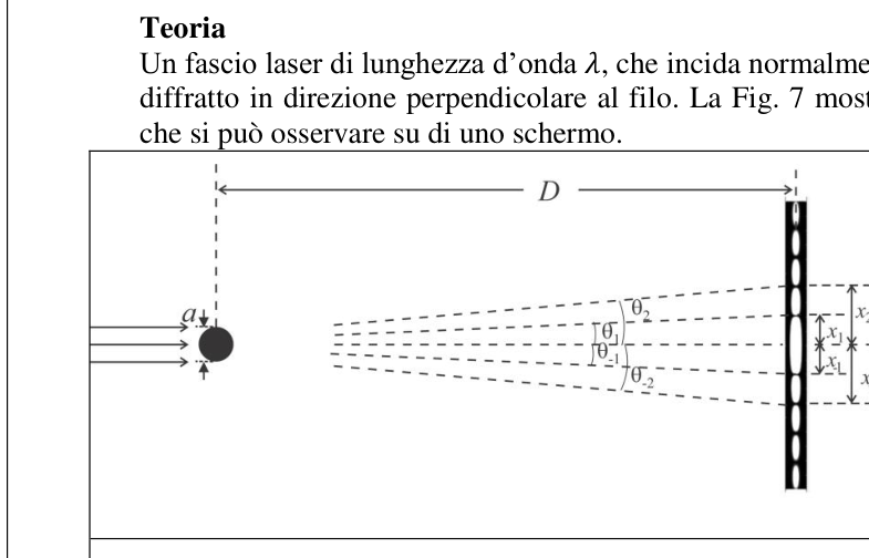
p.3 — Schema figura diffrazione da cilindro
p.4 — Insieme di sottili fili paralleli

Topic: Wave Optics Metodi: Physical Modeling Competenze: Measurement & Instrumentation Objects: Screen, Wire Fonte: Testo (PDF) — p.4 Soluzione: Soluzioni (PDF)
The following is the list of the following:
- Turn off the laser source. On the screen, with the springs, a figure detection sheet The Commission has not yet adopted a proposal.
The following table shows the results of the calculation of the weight of the product:
**p.4 ** Sets of thin parallel wires
Topic: Wave Optics Metodi: Physical Modeling Competenze: Measurement & Instrumentation Objects: Screen, Wire Fonte: Testo (PDF) — p.4 Soluzione: Soluzioni (PDF)
nuovamente il laser
- Fissa sullo schermo lo specchio piano in dotazione usando le mollette di plastica e accendi nuovamente il laser.
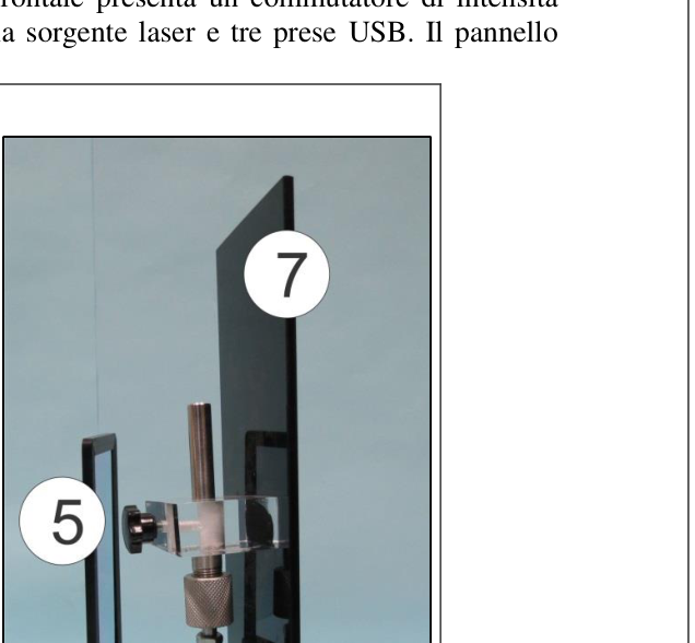
p.2 — Specchio di sinistra e schermo
Topic: Geometric Optics Metodi: Ray Tracing, Thin Lens & Mirror Equation Competenze: Diagrammatic Reasoning, Measurement & Instrumentation Objects: Mirror, Screen Fonte: Testo (PDF) — p.4 Soluzione: Soluzioni (PDF)
The laser is again MSK1/>
- Fix the equipped flat mirror on the screen using the plastic springs and turn on The laser again.
**p.2 ** Left mirror and screen
Topic: Geometric Optics Metodi: Ray Tracing, Thin Lens & Mirror Equation Competenze: Diagrammatic Reasoning, Measurement & Instrumentation Objects: Mirror, Screen Fonte: Testo (PDF) — p.4 Soluzione: Soluzioni (PDF)
- Regola lo schermo in modo che il raggio laser ripercorra all’indietro il suo cammino ritornando alla sorgente. Quando l’allineamento è completo, togli lo specchio.
p.3 — Disposizione schermo alternativa con cilindro

Topic: Geometric Optics Metodi: Ray Tracing, Thin Lens & Mirror Equation Competenze: Diagrammatic Reasoning, Measurement & Instrumentation Objects: Mirror, Screen, Cylinder Fonte: Testo (PDF) — p.4 Soluzione: Soluzioni (PDF)
- Adjust the screen so that the laser beam travels backwards in its path and backwards At the source. When the alignment is complete, remove the mirror.
The following table shows the dimensions of the screen:
Topic: Geometric Optics Metodi: Ray Tracing, Thin Lens & Mirror Equation Competenze: Diagrammatic Reasoning, Measurement & Instrumentation Objects: Mirror, Screen, Cylinder Fonte: Testo (PDF) — p.4 Soluzione: Soluzioni (PDF)
- Puoi accendere o spegnere la luce nella cabina come ti è più comodo.
Esperimento Parte A: Determinazione delle caratteristiche geometriche di una molla elicoidale Il campione I è una molla elicoidale di raggio e passo , costruita con un filo di spessore uniforme come mostrato in Fig. 10(a). La sua proiezione, osservata in direzione ortogonale, è equivalente a due insiemi di fili paralleli, dello stesso spessore, separati da una distanza e con un angolo tra di loro (Fig. 10(b)).
Figura 10: (a) Vista usuale di una molla elicoidale; (b) Diagramma schematico della vista a incidenza normale
Monta il campione I nel portacampioni, assicurandoti che la molla risulti verticale.
Devi ottenere una figura di diffrazione a forma di X, chiara e ben definita, sul foglio di rilevamento.
Figura 9: Insieme di quattro fili Page 5 of 6 E-I Q
A questo scopo, puoi regolare
la messa a fuoco del fascio laser (ruota il cappuccio con la lente)
l’orientamento del fascio (ruota il corpo del laser in modo che siano illuminate soltanto due spire della molla)
l’intensità del laser (commutatore high/low dell’alimentatore)
la luce ambiente (accendi/spegni la luce nella cabina) Se il massimo centrale è troppo luminoso, puoi appiccicare sul foglio di rilevamento gli adesivi neri rotondi, in modo da ridurre la diffusione.
Compito Descrizione Punti A1 Segna sul foglio di rilevamento (usando la matita in dotazione [13]) le posizioni opportune dei minimi di intensità per poter determinare e , da entrambi i lati della macchia centrale. Contrassegna i fogli di rilevamento con P-1, P-2 ecc. 0.7 A2 Con il calibro digitale, misura le distanze opportune per determinare e riportale nella Tabella A1. 0.5 A3 Disegna un grafico opportuno, contrassegnalo come Grafico A1 e determina dalla sua pendenza. 0.7 A4 Misura le distanze appropriate per determinare e riportale nella Tabella A2. 0.8 A5 Disegna un grafico opportuno, contrassegnalo come Grafico A2 e determina dalla sua pendenza. 0.6 A6 Determina l’angolo dalla figura a forma di X 0.2 A7 Esprimi in termini di e e calcola il valore di . 0.2 A8 Esprimi in termini di e e calcola il valore di (trascura ). 0.2
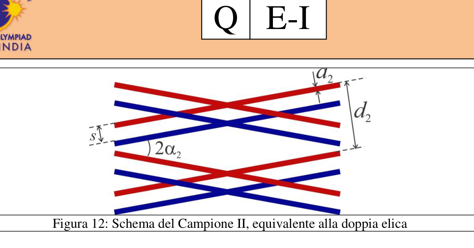
Parte B: Determinazione delle caratteristiche geometriche di una figura equivalente a una doppia elica La Figura 11(a) mostra due spire di una doppia elica. La Fig. 11( b) è una proiezione bidimensionale di questa doppia elica vista sotto un angolo normale. Ciascuna elica di spessore ha le spire che formano un angolo ; la distanza tra le spire in direzione perpendicolare è . La separazione tra le due eliche è . Il Campione II è uno schema equivalente a una doppia elica stampato su una lastrina di vetro (Fig. 12); la sua figura di diffrazione è simile a quella di una doppia elica. In questa parte dovrai determinare le caratteristiche geometriche del Campione II.
Figura 11: (a) Vista usuale di una molla a doppia elica (b) Diagramma schematico della stessa, vista con incidenza normale. Page 6 of 6 E-I Q
Figura 12: Schema del Campione II, equivalente alla doppia elica
Monta il Campione II nel portacampioni.
Fissa sullo schermo un altro foglio di rilevamento.
Fai in modo di avere sullo schermo una figura di diffrazione a forma di X, chiara e nitida.
Compiti Descrizione Punti B1 Segna le posizioni opportune dei minimi su ciascun lato della macchia centrale per determinare e . Puoi usare più di un foglio di rilevamento. 1.1 B2 Misura le distanze opportune per determinare e riportale nella Tabella B1. 0.5 B3 Disegna un grafico opportuno, contrassegnalo come Grafico B1 e determina dalla sua pendenza. 0.5 B4 Misura le distanze opportune per determinare e riportale nella Tabella B2. 1.2 B5 Disegna un grafico opportuno, contrassegnalo come Grafico B2 e determina dalla sua pendenza. 0.5 B6 Misura le distanze opportune per determinare e riportale nella Tabella B3. 1.6 B7 Disegna un grafico opportuno, contrassegnalo come Grafico B3 e determina dalla sua pendenza. 0.5 B8 Determina l’angolo dalla figura a forma di X. 0.2
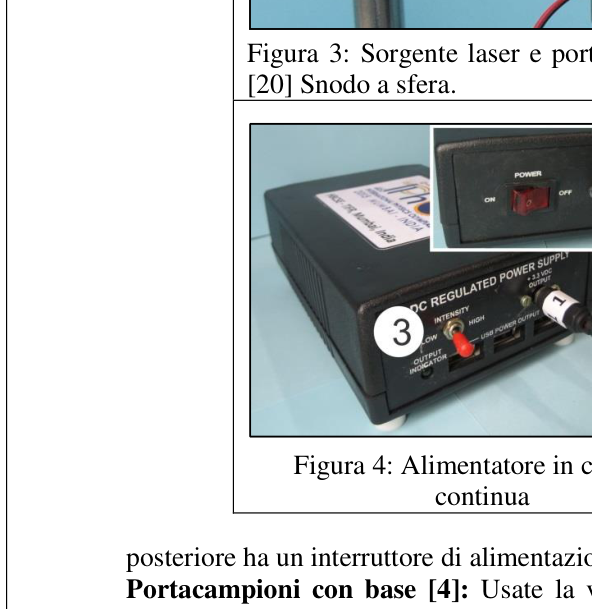
p.2 — Alimentatore di corrente continua
p.4 — Vista e diagramma molla elicoidale

p.5 — Molla a doppia elica e diagramma

p.6 — Schema Campione II equivalente a doppia elica
Topic: Wave Optics, Geometric Optics Metodi: Interference & Diffraction Analysis, Graph Linearization, Experimental Data Analysis Competenze: Experimental Data Analysis, Graph Linearization, Measurement & Instrumentation Objects: Spring, Wire, Screen Fonte: Testo (PDF) — p.4 Soluzione: Soluzioni (PDF)
- You can turn on or off the light in the cabin as you like.
Experiment Part A: Determination of the geometric characteristics of a helical spring Sample I is a beam and step helical spring , constructed with a uniform thickness wire as shown in Fig. 10(a). Its projection, observed in an orthogonal direction, is equivalent to Two sets of parallel wires of the same thickness, separated by a distance and at an angle between The Commission has already adopted a number of measures. 10(b)).
Figure 10: (a) The usual view of a helical spring; (b) Schematic diagram of normal incidence vision
Mount the sample I in the sample carrier, making sure the spring is vertical.
You need to get a clear, well-defined X-shaped diffraction figure on the sheet of The detection.
Figure 9: Together with four strings Page 5 of 6 E-I Q
For this purpose, you can adjust
The laser beam focusing (spins the cap with the lens)
The beam orientation (rotates the laser body so that only two are illuminated) (Spring breathing)
The laser intensity (high/low power switch)
ambient light (turn on/off the light in the cabin) If the center maximum is too bright, you can hang the black stickers on the detection sheet. rounded, so as to reduce the spread.
The task The following is the list of the following: Points A1 Mark on the survey sheet (using the pencil fitted [13]) the appropriate positions of the The maximum intensity to be determined and, on both sides of the central stain. Compare the test sheets with P-1, P-2 etc. 0.7 A2 Using the digital caliber, measure the appropriate distances to determine and report them in the Table A1. 0.5 A3 Draw an appropriate chart, mark it as chart A1 and determine by its The slope. 0.7 A4 Measure the appropriate distances to determine and report them in Table A2. 0.8 A5 Draw an appropriate chart, mark it as A2 and determine by its The slope. 0.6 A6 Determine the angle from the X-shaped figure 0.2 A7 Express in terms of e and calculate the value of . 0.2 A8 Express in terms of e and calculate the value of (negligence). 0.2
Part B: Determination of the geometric characteristics of a figure equivalent to a Double propellers Figure 11 (a) shows two spires of a double propeller. The Fig. 11( (b) is a two-dimensional projection of this double helix seen from a normal angle. Each propeller of this thickness has a spire that They form an angle; the distance between the spires in the perpendicular direction is . The separation between the Two propellers is . The Model II is a double propeller-like pattern printed on a sheet of The following table shows the results of the study: 12); its diffraction figure is similar to that of a double propeller. This part you have to determine the geometric characteristics of the sample II.
Figure 11: (a) A usual view of a double propeller spring (b) A diagram of the same, viewed with normal incidence. Page 6 of 6 E-I Q
Figure 12: Scheme of the Model II, equivalent to the double propeller
He’s putting the Champion II in the champion car.
Put another detection sheet on the screen.
Make sure you have an X-shaped diffraction figure on the screen, clear and sharp.
Tasks The following is the list of the following: Points B1 Indicate the appropriate positions of the minima on each side of the centre stain for Determine the e . You can use more than one trace sheet. 1.1 B2 Measure the appropriate distances to determine and report them to Table B1. 0.5 B3 Draw an appropriate chart, mark it as Chart B1 and determine by its The slope. 0.5 B4 Measure the appropriate distances to determine and report them to Table B2. 1.2 B5 Draw an appropriate chart, mark it as Chart B2 and determine by its The slope. 0.5 B6 Measure the appropriate distances to determine and report them to Table B3. 1.6 B7 Draw an appropriate chart, mark it as Chart B3 and determine by its The slope. 0.5 B8 Determine the angle from the X-shaped figure. 0.2
The power supply shall be provided by the manufacturer.
p.4 View and diagram of the helical spring
**p.5 ** Double propeller and diagram
The following is the list of the types of vehicles that are used:
Topic: Wave Optics, Geometric Optics Metodi: Interference & Diffraction Analysis, Graph Linearization, Experimental Data Analysis Competenze: Experimental Data Analysis, Graph Linearization, Measurement & Instrumentation Objects: Spring, Wire, Screen Fonte: Testo (PDF) — p.4 Soluzione: Soluzioni (PDF)