1. The Flywheel Chronicles
In the following experiment we are interested in determining the moment of inertia of a flywheel. The free ends of the axle in a flywheel assembly are placed inside grooves at both ends, to rigid supports provided on the wall (see diagram below). The diameter of the axle is . The total work done by the axle in overcoming the friction in the two grooves per rotation is . A massless string, attached to a point mass is wound tightly in turns (without overlap) on the axle. The string unwinds from the axle without slipping as the mass descends from an initial height . The length of the string is adjusted such that when the mass just touches the floor, the string detaches from the axle.
Quesito 1
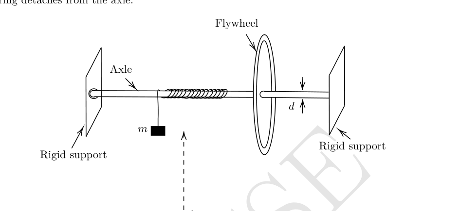
From the instant when the mass touches the floor (taken as ), the flywheel continues to rotate, adding another number of rotations before coming to rest in time . The figure is not to scale.
(a) [5 marks] Derive an expression for the moment of inertia of the flywheel in terms of , and other known parameters.
(b) [3 marks] The following data has been obtained in this experiment.
| (gm) | (sec) | |
|---|---|---|
| 150.0 | 145.25 | 190.0 |
| 200.0 | 200.00 | 225.5 |
| 250.0 | 238.50 | 235.5 |
Calculate the value of for , and .
Topic: Rotational Dynamics Metodi: Torque & Angular Momentum Analysis, Conservation of Energy Competenze: Experimental Data Analysis Objects: Wheel, String Fonte: Testo (PDF) — p.2 Soluzione: Soluzioni (PDF)
1. The Flywheel Chronicles
Nel seguente esperimento siamo interessati a determinare il momento di inerzia di un volante. Le estremità libere dell’asse di un montato di volante sono collocate all’interno di solvi alle entrambe le estremità, per supporti rigidi forniti sul muro (vedere diagramma di seguito). Il diametro dell’asse è . Il lavoro totale svolto dall’asse per superare l’attrito nelle due sollie per rotazione è . Una corda senza massa, attaccata a una massa puntaria , è strettamente rotata in (senza sovrapposizione) sull’asse. La corda si allontana dall’asse senza scivolare mentre la massa scende da un’altezza iniziale . La lunghezza della corda è regolata in modo tale che quando la massa tocca il pavimento, la corda si stacca dall’asse.
Quesito 1
Dal momento in cui la massa tocca il pavimento (preso ), il volante continua a ruotare, aggiungendo un altro numero di rotazioni prima di riposare nel tempo . La cifra non è scalabile.
a) [5 punti] Derivare un’espressione per il momento di inerzia del volante in termini di e di altri parametri noti.
b) [3 punti] I seguenti dati sono stati ottenuti in questo esperimento.
| (gm) | (sec) | |
|---|---|---|
| 150.0 | 145.25 | 190.0 |
| 200.0 | 200.00 | 225.5 |
| 250.0 | 238.50 | 235.5 |
Calcolare il valore di per e .
Topic: Rotational Dynamics Metodi: Torque & Angular Momentum Analysis, Conservation of Energy Competenze: Experimental Data Analysis Objects: Wheel, String Fonte: Testo (PDF) — p.2 Soluzione: Soluzioni (PDF)
2. Gearminator: Rise of the Machines
We consider a “thought experiment” involving a DC motor and a DC generator coupled mechanically through a gearbox, operating under idealized conditions, to explore the power output and efficiency of the system (see schematic figure below). The schematic gearbox assembly is also shown in the figure.
Quesito 2
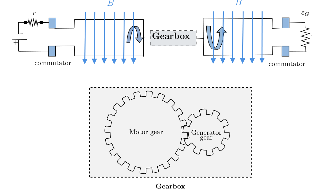
Both the motor and the generator have loops of area and rotate in a uniform magnetic field of strength . As usual, both the motor and the generator use commutators (indicated by the blue blocks) to reverse the direction of current in each arm every half cycle, to ensure unidirectional output. The generator is connected to an external resistance , and the motor is driven by a constant voltage with an internal resistance . The gearbox is idealized, with no energy loss due to friction or otherwise, and no slipping between the teeth of the gears. For a pair of meshing gears, as shown above, the angular speed ratio, also known as the gear ratio , is defined as: where and are the angular velocities of the motor and the generator, respectively. Let , and be the time-averaged generator output power and the time-averaged motor input power, respectively, over one complete cycle.
(a) [6 marks] Derive the expression for in terms of , and the given parameters. For fixed values of and , determine the expression of for which is maximum.
(b) [3 marks] Derive the expression for the generator output power in terms of , and the given parameters. For fixed values of and , determine the expression of for which is maximum.
(c) [5 marks] For fixed values of and , determine the condition on for which the efficiency is maximum, where Calculate this maximum value of .
Topic: Electromagnetic Induction Metodi: Faraday’s Law of Induction, Torque & Angular Momentum Analysis Competenze: Mathematical Modeling Objects: Gear, Coil Fonte: Testo (PDF) — p.3 Soluzione: Soluzioni (PDF)
2. Giro: Rising delle macchine
Si considera un “esperimento di pensiero” che coinvolge un motore a corrente continua e un generatore a corrente continua accoppiati meccanicamente attraverso una scatola di ingranaggi, operando in condizioni idealizzate, per esplorare la potenza di uscita e l’efficienza del sistema (vedere figura schematica qui sotto). Il montaggio schematico della casella di cambio è anche mostrato nella figura.
Quesito 2
Sia il motore che il generatore hanno un’area di buchi e ruotano in un campo magnetico uniforme di resistenza . Come al solito, sia il motore che il generatore utilizzano commutatori (indicati dai blocchi blu) per invertire la direzione della corrente in ciascun braccio ogni mezzo ciclo, per garantire un’uscita unidirezionale. Il generatore è collegato a una resistenza esterna e il motore è alimentato da una tensione costante con una resistenza interna . La casella di ingranaggi è idealizzata, senza perdita di energia a causa di attrito o altro, e senza scivolamento tra i denti delle engranaggi. Per un paio di ingranaggi di maglia, come indicato sopra, il rapporto di velocità angolare, noto anche come rapporto di ingranaggio , è definito come: dove e sono rispettivamente le velocità angolari del motore e del generatore. La potenza di uscita del generatore media temporanea e la potenza di ingresso del motore media temporanea, rispettivamente, su un ciclo completo, sono e .
a) [6 segni] Derivare l’espressione per in termini di e dei parametri forniti. Per i valori fissi di e , determinare l’espressione di per la quale è massimo.
b) [3 punti] Derivare l’espressione per la potenza di uscita del generatore in termini di e dei parametri indicati. Per i valori fissi di e , determinare l’espressione di per la quale è massimo.
c) [5 marchi] Per i valori fissi di e , determinare la condizione su per la quale l’efficienza è massima, se Calcolare questo valore massimo di .
Topic: Electromagnetic Induction Metodi: Faraday’s Law of Induction, Torque & Angular Momentum Analysis Competenze: Mathematical Modeling Objects: Gear, Coil Fonte: Testo (PDF) — p.3 Soluzione: Soluzioni (PDF)
3. Love is in the air
A thermodynamic cycle is performed for one mole of an ideal monoatomic gas. The representation of this cycle is in the shape of a “heart” in the volume () – temperature () graph (shown as the shaded area below). However, neither of the axes are provided in the graph. The graph is drawn to scale with 1 cm along the -axis representing 4 litre, and 1 cm along the -axis representing 80 K.
It is given that the pressure at the point is minimum for the whole cycle, with the temperature and volume at this point being and litre.
Quesito 3
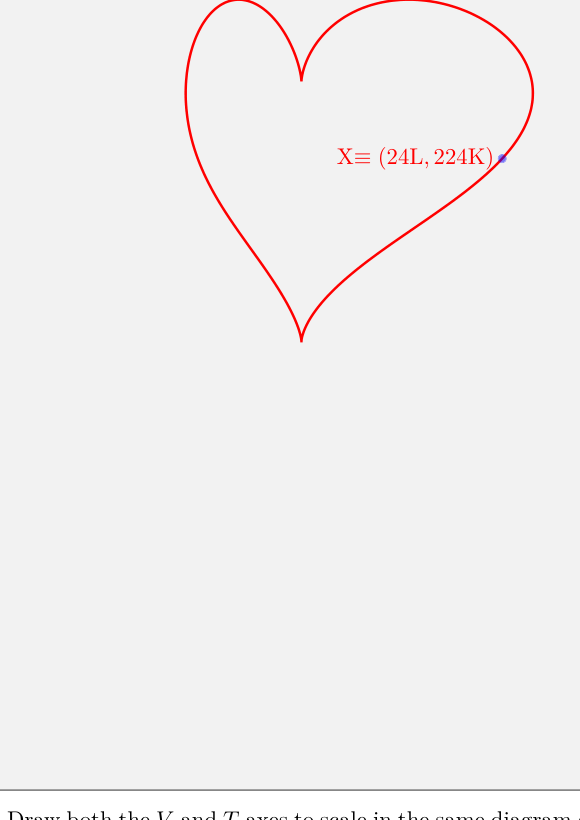
(a) [13 marks] Draw both the and axes to scale in the same diagram given in the Summary Answersheet. Indicate the origin by “O”. Justify your answer in the detailed answersheet. You are given one extra answer box in the answersheet, in case of any mistake in the first.
(b) [3 marks] For the axes and origin you have drawn, indicate the point(s) on the graph where the pressure is/are maximum in the cycle by and label it as on the curve. Determine the value of the maximum pressure.
Topic: Thermodynamics Metodi: Thermodynamic Cycle Analysis, Ideal Gas Law Competenze: Diagrammatic Reasoning Objects: Gas Fonte: Testo (PDF) — p.3 Soluzione: Soluzioni (PDF)
**3. L’amore è nell’aria
Un ciclo termodinamico viene eseguito per un mole di gas monoatomo ideale. La rappresentazione di questo ciclo è in forma di “cuore” nel grafico di temperatura () () (indicato come la zona ombrata di seguito). Tuttavia, nessuno degli assi è indicato nel grafico. Il grafico è disegnato in scala con 1 cm lungo l’asse che rappresenta 4 litri e 1 cm lungo l’asse che rappresenta 80 K.
Si ritiene che la pressione al punto sia minima per tutto il ciclo, con la temperatura e il volume a questo punto e litri.
Quesito 3
(a) [13 punti] Disegnare gli assi e per scalare nello stesso diagramma riportato nella scheda di risposte di sintesi. Indicare l’origine con “O”. giustifica la tua risposta nella scheda dettagliata. Vi viene data una casella di risposta in più nella scheda di risposta, in caso di errore nella prima.
b) [3 punti] Per gli assi e l’origine disegnati, indicare il punto (s) sul grafico dove la pressione è/sono massima nel ciclo di e etichettarlo come sulla curva. Determinare il valore della pressione massima.
Topic: Thermodynamics Metodi: Thermodynamic Cycle Analysis, Ideal Gas Law Competenze: Diagrammatic Reasoning Objects: Gas Fonte: Testo (PDF) — p.3 Soluzione: Soluzioni (PDF)
4. The Magnetic Black Box (MBB)
A magnetometer is a Hall-effect-based sensor that measures the magnetic field at its location. In the figure below, a magnetometer is located somewhere inside a closed “magnetic black box” (which we shall henceforth refer to as MBB) of negligible thickness. Fig. (1) gives a top view, where the red rectangle depicts the MBB. The plane of the rectangle is taken as the – plane of coordinates, with the origin O taken at the top right corner. The unknown location of the magnetometer is denoted by the coordinates . For example, it could be located at the position marked by inside the MBB. Note that the actual location of the magnetometer inside the MBB may be different from that in the figure; this is true for all subsequent figures in this problem as well.
Quesito 4
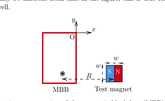
The components , and of the magnetic field measured by the magnetometer depend on the strength and the orientation of the magnetic dipole moment, of a magnet positioned nearby and the distance between the center of the magnet and the magnetometer. The effect of the Earth’s magnetic field is neglected throughout this problem.
Vanya is performing an experiment using the MBB. She has to first locate the exact position of the magnetometer inside the MBB. She has a cubical test magnet of side length (see Fig. (1)) and unknown dipole strength .
She places the MBB on a wooden table. Then she records the magnetic field values displayed by the magnetometer as the test magnet is moved either parallel to the -axis while keeping fixed (vertical scan) or parallel to the -axis while keeping fixed (horizontal scan) as shown in Fig. (2). The magnitudes of the distances, and , measured from the center of the magnet, are also shown in the figure.
Quesito 4
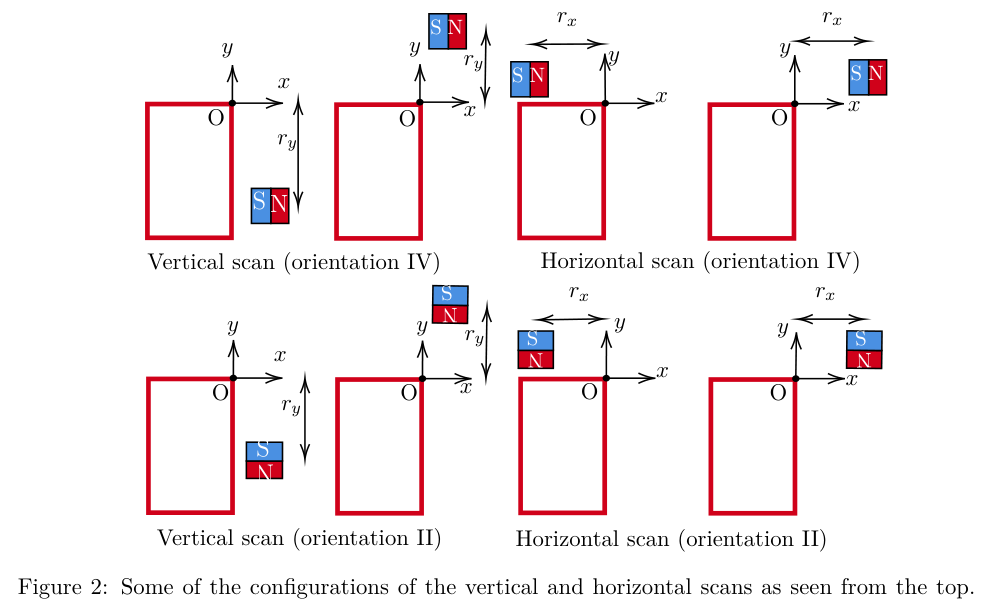
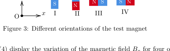
For each scan, Vanya also tries different orientations of the magnet by aligning the dipole moment vector either parallel or anti-parallel to the -axis or -axis. The different orientations (I to IV) are shown in Fig. (3). During the experiment, assume that the magnetometer location and the magnet’s center are at the same height (i.e., their -coordinates are always the same).
Quesito 4
The graphs in Fig. (4) display the variation of the magnetic field for four of the vertical and horizontal scans (denoted by A, B, C, D) with certain combinations of the orientations.
Quesito 4
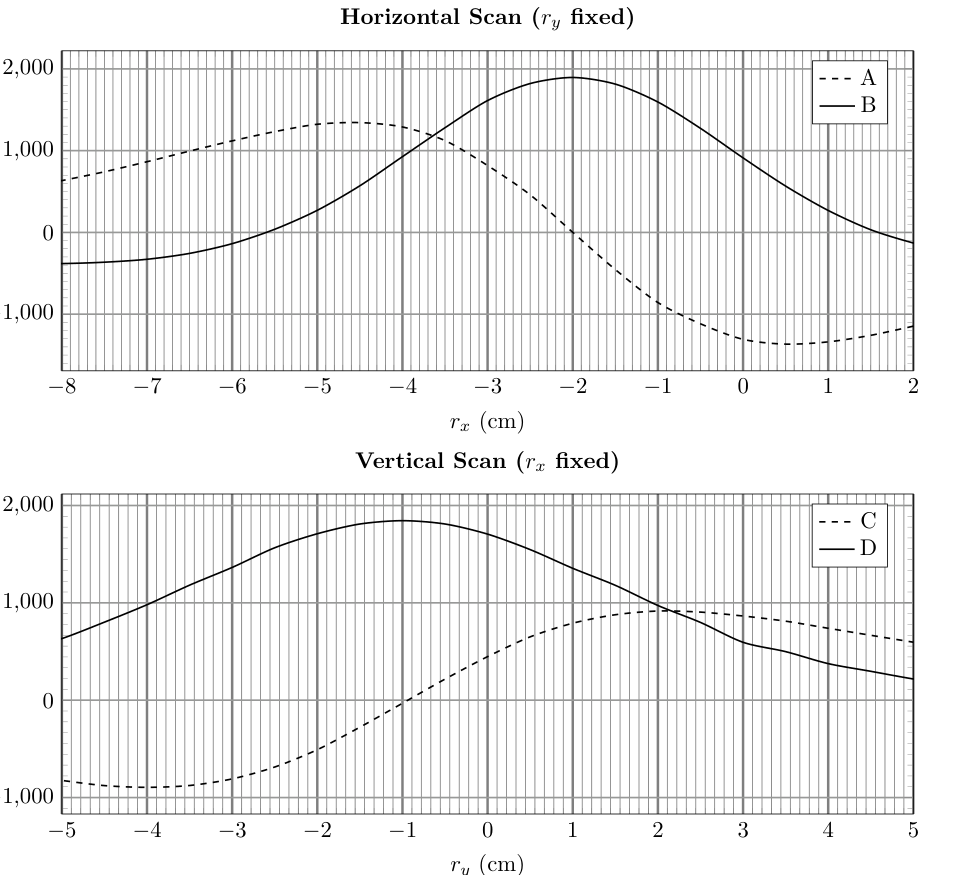
(a) [7 marks] Based on the above plots, identify which orientations (I-IV) these curves belong to. To indicate your answer, fill in the table in the answersheet. Determine the coordinates of the magnetometer’s position. You must justify your answers.
(b) Vanya is given two cuboidal magnetic sets M1 and M2, each constructed using two identical cubic magnets (of side length ). In set M1, two magnets, each of dipole moment , are joined in an attractive configuration. In set M2, the magnets are joined in a repulsive configuration using a strong adhesive. Thus, each magnetic set has a length of (as shown in Fig. (5)).
Quesito 4
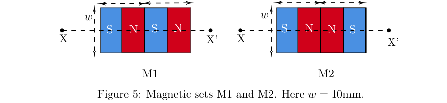
Vanya aligns the central axis (XX’ in Fig. (5)) of one magnetic set M1 or M2 such that the central axis passes through the magnetometer and is parallel to the -axis. A representation of the setup is shown in Fig. 6. By keeping the -coordinate fixed at , Vanya moves the magnetic set parallel to the -axis. The distance from the magnetometer to the midpoint of the magnetic set is . For each position, she measures the distance (the distance from the face of the MBB to the nearest edge of the magnetic set) and the corresponding magnetic field component, .
Quesito 4
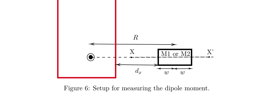
i. [5 marks] For the case of , obtain expressions for the net magnetic field at the magnetometer due to M1 and M2 in terms of , , , and other constants. You may assume that each individual magnet can be modelled as a pair of magnetic monopoles separated by a distance .
ii. [10 marks] One set of Vanya’s data is presented in the table below.
| (cm) | () | (cm) | () |
|---|---|---|---|
| 2.1 | -1359 | 3.1 | -646 |
| 2.3 | -1168 | 3.3 | -563 |
| 2.5 | -1001 | 3.5 | -493 |
| 2.7 | -855 | 3.7 | -447 |
| 2.9 | -743 | 3.9 | -398 |
Plot a suitable linear graph to analyze the data, and from the graph, identify whether the data belongs to M1 or M2. Justify your answer. From the same linear plot (or a different one), calculate of the individual magnets used in constructing the magnetic set.
Topic: Magnetism Metodi: Physical Modeling, Vector Decomposition Competenze: Measurement & Instrumentation Objects: Magnet, Magnetic Dipole Fonte: Testo (PDF) — p.4 Soluzione: Soluzioni (PDF)
**4. La scatola nera magnetica (MBB) **
Un magnetometro è un sensore basato sull’effetto Hall che misura il campo magnetico nella sua posizione. Nella figura seguente, un magnetometro si trova da qualche parte all’interno di una “quadro nero magnetico” chiuso (che da ora in poi si riferirà a come MBB) di spessore trascurabile. Fig. - Cosa? (1) dà una vista in alto, dove il rettangolo rosso raffigura l’MBB. Il piano del rettangolo è preso come il piano delle coordinate x$$y, con l’origine O presa nell’angolo superiore destro. La posizione sconosciuta del magnetometro è indicata dalle coordinate . Ad esempio, potrebbe essere situato nella posizione segnata da all’interno dell’MBB. Si noti che la posizione effettiva del magnetometro all’interno del MBB può essere diversa da quella della figura; questo vale anche per tutte le figure successive di questo problema.
Quesito 4
I componenti , e del campo magnetico misurato dal magnetometro dipendono dalla forza e dall’orientamento del momento di dipolo magnetico, da un magnete posizionato nelle vicinanze e dalla distanza tra il centro del magnete e il magnetometro. L’effetto del campo magnetico terrestre è trascurato in tutto questo problema.
Vanya sta facendo un esperimento usando l’MBB. Deve prima localizzare la posizione esatta del magnetometro all’interno del MBB. Essa dispone di un magnete di prova cubico di lunghezza laterale (vedi figura. (1)) e resistenza dipolare sconosciuta .
Mette l’MBB su un tavolo di legno. Poi registra i valori del campo magnetico visualizzati dal magnetometro quando il magnete di prova viene spostato sia parallelo all’asse mantenendo il fisso (scansaggio verticale) sia parallelo all’asse mantenendo il fisso (scansaggio orizzontale) come mostrato nella figura. (2). Le magnitudini delle distanze, e , misurate dal centro del magnete, sono anche illustrate nella figura.
Quesito 4
Per ogni scansione, Vanya prova anche diversi orientamenti del magnete allineando il vettore del momento di dipole sia parallelo che antiparallelo all’asse o all’asse . Le differenti orientamenti (I a IV) sono illustrate nella figura. (3). Durante l’esperimento, supponiamo che la posizione del magnetometro e il centro del magnete siano alla stessa altezza (cioè le loro coordinate sono sempre le stesse).
Quesito 4
I grafici in Fig. (4) mostrare la variazione del campo magnetico per quattro delle scansioni verticali e orizzontali (indicate da A, B, C, D) con determinate combinazioni di orientamenti.
Quesito 4
(a) [7 punti] Sulla base dei diagrammi di cui sopra, identificare a quali orientamenti (I-IV) appartengono queste curve. Per indicare la risposta, compila la tabella della scheda. Determinare le coordinate della posizione del magnetometro. Devi giustificare le tue risposte.
b) Vanya riceve due set magnetici cuboidi M1 e M2, ciascun costruito utilizzando due magneti cubi identici (di lunghezza laterale ). Nel set M1, due magneti, ciascuno di momento di dipolo , sono uniti in una configurazione attraente. Nel set M2, i magneti sono uniti in una configurazione repulsiva utilizzando un adesivo forte. Pertanto, ogni set magnetico ha una lunghezza di (come mostrato nella figura. (5)).
Quesito 4
Vanya allinea l’asse centrale (XX’ nella figura. (5)) di un insieme magnetico M1 o M2 in modo tale che l’asse centrale attraversare il magnetometro ed essere parallelo all’asse . Una rappresentazione della configurazione è mostrata nella figura. 6. Tenendo la coordinata fissa a , Vanya muove l’insieme magnetico parallelo all’asse . La distanza dal magnetometro al punto medio dell’insieme magnetico è . Per ciascuna posizione, misura la distanza (la distanza dalla superficie del MBB al bordo più vicino dell’insieme magnetico) e la corrispondente componente del campo magnetico, .
Quesito 4
i. [5 punti] Per , ottenere espressioni per il campo magnetico netto al magnetometro dovuto a M1 e M2 in termini di , , e altre costanti. Si può supporre che ogni singolo magnete possa essere modellato come una coppia di monopoli magnetici separati da una distanza .
ii. [10 punti] Un insieme di dati di Vanya è presentato nella tabella seguente.
| (cm) | () | (cm) | () |
|---|---|---|---|
| 2.1 | -1359 | 3.1 | -646 |
| 2.3 | -1168 | 3.3 | -563 |
| 2.5 | -1001 | 3.5 | -493 |
| 2.7 | -855 | 3.7 | -447 |
| 2.9 | -743 | 3.9 | -398 |
Tracciare un grafico lineare adatto per analizzare i dati e, a partire dal grafico, identificare se i dati appartengono a M1 o M2. giustifica la tua risposta. Dal medesimo grafico lineare (o di un altro), calcolare dei singoli magneti utilizzati per costruire l’insieme magnetico.
Topic: Magnetism Metodi: Physical Modeling, Vector Decomposition Competenze: Measurement & Instrumentation Objects: Magnet, Magnetic Dipole Fonte: Testo (PDF) — p.4 Soluzione: Soluzioni (PDF)
5. Metalens
A metasurface is a two-dimensional, ultra-thin optical structure consisting of an array of nano-spaced optical nano-elements (also known as meta-atoms) on a flat surface (typically an ultra-thin glass plate). The primary function of the nano-elements is to locally introduce a phase shift to the wave, incident at position . This function, , is called the phase profile of the metasurface. Metalens has a circular metasurface with a circularly symmetric phase profile function, , which depends on the distance of the point from the center of the metalens (see figure below). This type of metalens can be used for focusing incoming parallel rays to a point. Unlike normal lenses, the metalens will look just like an ultrathin circular disc.
Consider two homogeneous media of refractive indices and separated by a metalens as shown in the figure below. Suppose a beam of plane wave is incident at point Q (at distance from the pole P) on the metasurface at an angle of from medium 1. Assume that the rays falling at Q are in the plane containing PQ and the axis of the lens (- plane). These rays will be refracted at an angle in the medium 2. The angle of refraction depends on . Thus, the modified law of refraction for the metasurface can be written as Similarly, the rays falling at , at a distance , will be refracted by an angle .
Quesito 5
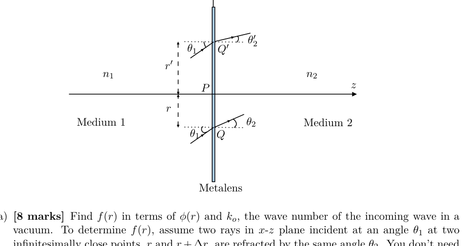
(a) [8 marks] Find in terms of and , the wave number of the incoming wave in a vacuum. To determine , assume two rays in - plane incident at an angle at two infinitesimally close points, and , are refracted by the same angle . You don’t need to derive the exact functional form of for this part.
(b) [4 marks] Derive an expression for the phase profile , to convert a plane wavefront to spherical wavefront, with light being focused to a point F on the axis (see figure below), which is at a distance from the pole P.
Quesito 5
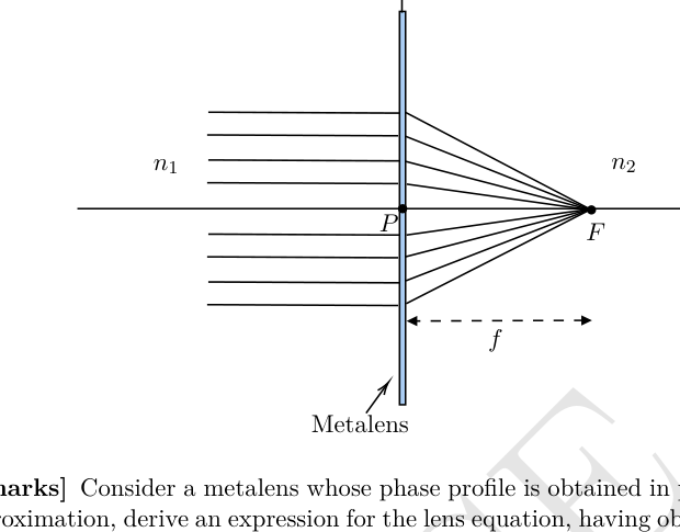
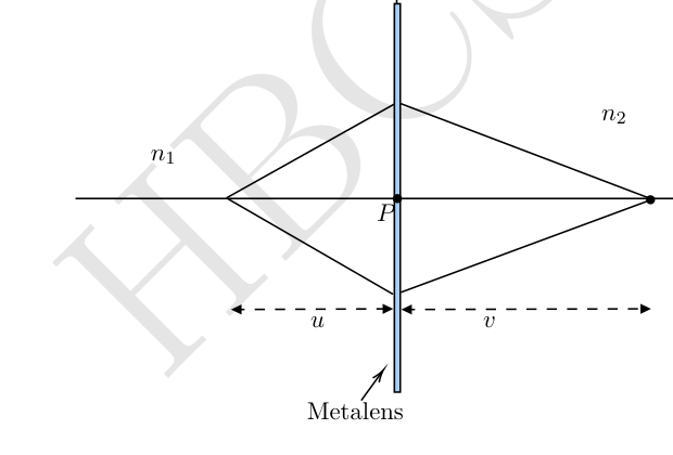
(c) [3 marks] Consider a metalens whose phase profile is obtained in part (b). For the paraxial approximation, derive an expression for the lens equation, having object distance and image distance being , with focal length (see figure below).
Quesito 5
Topic: Wave Optics, Geometric Optics Metodi: Interference & Diffraction Analysis, Snell’s Law Competenze: Mathematical Modeling Objects: Lens Fonte: Testo (PDF) — p.8 Soluzione: Soluzioni (PDF)
5. Metalli
Una meta-superficie è una struttura ottica bidimensionale e ultra-sottile costituita da un array di nano-elementi ottici spaziali (noto anche come meta-atomi) su una superficie piatta (tipolarmente una piastra di vetro ultra-sottile). La funzione primaria dei nanoelementi è quella di introdurre localmente un spostamento di fase all’onda, incidente alla posizione . Questa funzione, , è chiamata il profilo di fase della meta-superficie. Metalens ha una meta-superficie circolare con una funzione di profilo di fase simmetrica circolare, , che dipende dalla distanza del punto dal centro dei metalens (vedere figura seguente). Questo tipo di metalene può essere utilizzato per concentrare i raggi paralleli in arrivo su un punto. A differenza delle normali lenti, i metalli sembreranno proprio come un disco circolare ultratinto.
Considerate due media omogenei di indici di rifrazione e separati da un metalene come mostrato nella figura seguente. Supponiamo che un fascio di onda piana si incida al punto Q (a distanza dal polo P) sulla meta-superficie ad un angolo dal mezzo 1. Supponiamo che i raggi che cadono a Q siano nel piano contenente PQ e nell’asse della lente (piano -). Questi raggi saranno rifrazionati ad un angolo nel mezzo 2. L’angolo di rifrazione dipende da . Pertanto, la legge modificata di rifrazione per la meta-superficie può essere scritta come Allo stesso modo, i raggi che cadono a , a una distanza , saranno rifracciati da un angolo .
Quesito 5
a) [8 punti] Trova in termini di e , il numero d’onda dell’onda in entrata in vuoto. Per determinare , supponiamo che due raggi nel piano - incidenti ad un angolo a due punti infinitesimalmente vicini, e , siano refratti dallo stesso angolo . Non è necessario derivare la forma funzionale esatta di per questa parte.
b) [4 punti] Derivare un’espressione per il profilo di fase , per convertire un fronte d’onda piano in fronte d’onda sferica, con la luce focalizzata su un punto F sull’asse (vedi figura seguente), che è a una distanza dal polo P.
Quesito 5
(c) [3 marchi] Considerare un metalene il cui profilo di fase è ottenuto nella parte (b). Per l’approssimazione paraxiale, derivare un’espressione per l’equazione dell’obiettivo, con distanza dell’oggetto e distanza dell’immagine , con distanza focale (vedere figura seguente).
Quesito 5
Topic: Wave Optics, Geometric Optics Metodi: Interference & Diffraction Analysis, Snell’s Law Competenze: Mathematical Modeling Objects: Lens Fonte: Testo (PDF) — p.8 Soluzione: Soluzioni (PDF)