Electric currents in volume [15 points]
Experimental competition — 18 January 2012. The experimental competition consists of one problem and lasts 3 hours.
Instruments and equipment: Vessel 250 ml, two steel spokes, multimeter, power supply (4.5 V battery), resistor with a resistance of several kΩ, two-pole switch, plastic tube for a cocktail, connecting wires, clean water, plastic cup, rubber, ruler, and adhesive tape.
You should be familiar with the formula for calculating the resistance of a thin cylindrical conductor,
where is the specific resistance of the conducting material, is its length, is its cross-sectional area.
However, when an electric current flows in a bulk system, trajectories of charged particles may be different, so the resistance of the medium depends on the nature of the distribution of electric currents. You have to measure the electric resistance of the water layer when the current flows between the spokes submerged in water.
From time to time clean the spokes with rubber. After each series of experiments, change water in the vessel. Do not apply strong current through the water because this leads to appearance of a large number of ions in that can “spoil” the results of your experiments. Straighten the spokes. In all the experiments try to maintain the spokes in parallel to each other.
Part 1. [0.5 points]
1.1 Measure the resistance of the given resistor by using the multimeter. Record the result of your measurement.
To measure the resistance of the water between the spokes, use an electric circuit shown in the figure on the right. Here, is the given resistor, is the resistance of the water between the spokes to be measured.
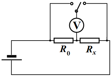
1.2 For this circuit write down the formula which will be used by you to calculate the water resistance between the spokes.
In the following, please use only the circuit above to obtain the resistance ! In any case do not measure water resistance directly by the multimeter. Use multimeter only as a voltmeter. Direct measurement of the resistance with a multimeter leads to a rapid discharge of its battery, and in addition, the voltage of the battery is rather high (9 V) to change the electrical properties of water.
Error analysis is not required in this Competition.
Part 2. [5 points]
Put the two spokes provided along the vessel walls keeping them in parallel at a maximum distance from each other. Bend the upper ends of the spokes over the edges of the vessel. Additionally fix them with strips of adhesive tape. To measure the height of the water level use the scale engraved on the vessel. Determine in millimeters the grating period of the scale engraved on the vessel wall.
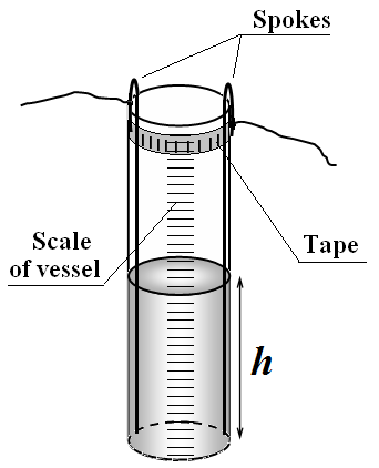
2.1 Measure dependence of the water resistance between the spokes as a function of the height of water poured into the vessel. Plot the obtained dependence in a graph.
2.2 Draw schematic streamlines of electric current in this case (make two draws: one in the plane of the spokes and the other in the plane perpendicular to the spokes).
Streamlines of electric current are trajectories of charged particles.
2.3 On the basis of physical considerations about the nature of this current flow, make an assumption about the form of the obtained experimental dependence , and write it as a formula.
2.4 Using the linearization method, check the validity of the made assumption by plotting a graph in such coordinates that it becomes a straight line . Determine the numerical values of the parameters of the linearized dependence, as well as the unknown values of parameters entering the function .
Part 3. [3.5 points]
Fix one spoke close to the wall inside the vessel. Pour 200 ml of water into the vessel. Move the second spoke along the wall, changing the distance between the spokes. The depth of immersion of the second spoke should be maximal. Spokes should be positioned vertically and in parallel to each other.
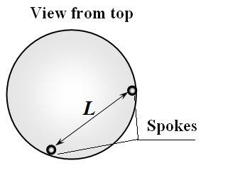
3.1 Measure the water resistance between the spokes as a function of the distance between them. Plot the obtained dependence.
3.2 On the basis of physical considerations about the nature of this current flow, make an assumption about the form of the obtained experimental dependence , and write it as a formula.
3.3 Using the linearization method, check the validity of the made assumption by plotting a graph in such coordinates that it becomes a straight line . Determine the numerical values of the parameters of the linearized dependence, as well as unknown values of parameters entering the function .
Part 4. [4 points]
Put one spoke into the given plastic tube so that its lower end of a length of about 1 cm remains uncovered by the tube. Fill the vessel with water about to top end. The upper edge of the tube should be placed above the water level, and fixed to the spoke by the tape. Put the second uncovered spoke into the water keeping its lower end at different heights. Keep the spokes in parallel at a maximum distance from each other.
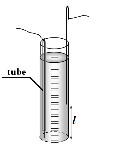
4.1 Measure the water resistance between the spokes as a function of the height of the end of the second spoke. Plot the obtained dependence in a graph.
4.2 Draw a schematic streamlines of electric current in this case (in the plane of the spokes).
4.3 On the basis of physical considerations on the nature of current flow, make an assumption about the form of the obtained experimental dependence , and write it as a formula.
4.4 In the plot, specify the range of values of in which the assumed formula for is confirmed experimentally.
4.5 Determine the numerical values of the parameters entering the assumed formula for .
Part 5. [2 points]
5.1 On the basis of the above obtained experimental data (please choose which one to use) estimate the specific resistance of the water .
Correnti elettriche in un volume [15 punti]
Prova sperimentale — 18 gennaio 2012. La prova sperimentale consiste in un unico problema e dura 3 ore.
Strumenti ed attrezzature: recipiente da 250 ml, due ferri (aghi) d’acciaio, multimetro, alimentatore (batteria da 4,5 V), resistore con una resistenza di diversi kΩ, interruttore a due poli, cannuccia di plastica da cocktail, cavi di collegamento, acqua pulita, tazza di plastica, gomma, righello e nastro adesivo.
Dovreste conoscere la formula per calcolare la resistenza di un conduttore cilindrico sottile,
dove è la resistenza specifica del materiale conduttore, è la sua lunghezza, è l’area della sua sezione trasversale.
Tuttavia, quando una corrente elettrica scorre in un mezzo esteso, le traiettorie delle particelle cariche possono essere diverse; pertanto la resistenza del mezzo dipende dalla natura della distribuzione delle correnti elettriche. È necessario misurare la resistenza elettrica dello strato d’acqua quando la corrente scorre tra i ferri immersi nell’acqua.
Di tanto in tanto pulite i ferri con la gomma.
Dopo ogni serie di esperimenti cambiate l’acqua nel recipiente.
Non fate passare correnti intense attraverso l’acqua, poiché ciò potrebbe causare la formazione di un gran numero di ioni che possono “rovinare” i risultati degli esperimenti.
Raddrizzate i ferri. In tutti gli esperimenti cercate di mantenerli paralleli tra loro.
Parte 1. [0,5 punti]
1.1 Misura la resistenza del resistore dato utilizzando il multimetro. Registra il risultato della tua misurazione.
Per misurare la resistenza dell’acqua tra i ferri, utilizza il circuito elettrico mostrato nella figura a destra. Qui, è il resistore dato, mentre è la resistenza dell’acqua da misurare.
1.2 Per questo circuito, scrivere la formula che verrà utilizzata per calcolare la resistenza dell’acqua tra i ferri.
Si prega di utilizzare esclusivamente il circuito sopra descritto per determinare la resistenza ! In ogni caso, non misurare direttamente la resistenza dell’acqua con un multimetro; utilizzarlo soltanto come voltmetro.
La misurazione diretta della resistenza con un multimetro provoca una rapida scarica della sua batteria, inoltre la tensione della batteria è abbastanza elevata (9 V) da alterare le proprietà elettriche dell’acqua.
In questa competizione non è richiesta l’analisi degli errori.
Parte 2. [5 punti]
Disponete i due ferri forniti lungo le pareti del recipiente, mantenendoli paralleli e a una distanza massima l’uno dall’altro. Piegate le estremità superiori dei ferri sopra il bordo del recipiente e fissateli inoltre con strisce di nastro adesivo. Per misurare l’altezza del livello dell’acqua, usate la scala incisa sul recipiente. Determinate in millimetri il passo della scala incisa sulla parete del recipiente.
2.1 Misurare la dipendenza della resistenza dell’acqua tra i ferri in funzione dell’altezza dell’acqua versata nel recipiente. Tracciare il grafico che rappresenta questa dipendenza.
2.2 Disegnare le linee di corrente elettrica schematiche in questo caso (realizzare due disegni: uno nel piano dei ferri e l’altro nel piano perpendicolare ai ferri).
Le linee di corrente elettrica rappresentano le traiettorie delle particelle cariche.
2.3 Sulla base di considerazioni fisiche riguardanti la natura di questo flusso di corrente, formulare un’ipotesi sulla forma della dipendenza sperimentale ottenuta e scriverla sotto forma di formula.
2.4 Utilizzando il metodo di linearizzazione, verificare la validità dell’ipotesi formulata tracciando un grafico in coordinate tali che la relazione appaia come una retta di tipo . Determinare i valori numerici dei parametri della dipendenza linearizzata, nonché i valori sconosciuti dei parametri che entrano nella funzione .
Parte 3. [3,5 punti]
Fissate un ferro vicino alla parete, all’interno del recipiente. Versate 200 ml d’acqua nel recipiente. Spostate il secondo ferro lungo la parete, variando la distanza tra i ferri. La profondità di immersione del secondo ferro deve essere massima. I ferri devono essere verticali e paralleli tra loro.
3.1 Misurare la resistenza dell’acqua tra i ferri in funzione della distanza che li separa. Tracciare il grafico della relazione ottenuta.
3.2 Sulla base di considerazioni fisiche riguardanti la natura di questo flusso di corrente, formulare un’ipotesi sulla forma della relazione sperimentale e esprimerla sotto forma di formula.
3.3 Utilizzando il metodo di linearizzazione, verificare la validità dell’ipotesi formulata tracciando un grafico in coordinate tali che la relazione appaia come una retta di tipo . Determinare i valori numerici dei parametri della relazione linearizzata, nonché i valori sconosciuti dei parametri che entrano nella funzione .
Parte 4. [4 punti]
Inserite un ferro nella cannuccia di plastica fornita, in modo che la sua estremità inferiore resti scoperta per circa 1 cm. Riempite il recipiente d’acqua quasi fino all’orlo. Il bordo superiore della cannuccia deve trovarsi sopra il livello dell’acqua ed essere fissato al ferro con il nastro adesivo. Immergete nell’acqua il secondo ferro, scoperto, tenendo la sua estremità inferiore a diverse altezze. Mantenete i ferri paralleli e alla massima distanza l’uno dall’altro.
4.1 Misurare la resistenza dell’acqua tra i ferri in funzione dell’altezza dell’estremità del secondo ferro. Tracciare il grafico che rappresenta questa dipendenza.
4.2 Disegnare schematicamente le linee di corrente elettrica in questo caso (nel piano dei ferri).
4.3 Sulla base di considerazioni fisiche riguardanti la natura del flusso di corrente, formulare un’ipotesi sulla forma della dipendenza sperimentale ottenuta e esprimerla sotto forma di formula.
4.4 Nel grafico, indicare l’intervallo di valori di per cui l’ipotizzata formula per viene confermata sperimentalmente.
4.5 Determinare i valori numerici dei parametri che entrano nella formulazione ipotizzata per .
Parte 5. [2 punti]
5.1 Sulla base dei dati sperimentali ottenuti in precedenza (si prega di scegliere quelli da utilizzare), stimare la resistività dell’acqua .