Рекламные трюки [15 баллов]
Экспериментальный тур — 16 января 2013 года. Экспериментальный тур состоит из одной задачи, продолжительность тура 3 часа.
Оборудование: Лазер, штатив с зажимом, собирающая линза на подставке, картонный экран, миллиметровая бумага, две направляющие линейки, измерительная линейка, пластинка с тремя оптическими элементами:
- Зеркало Френеля (квадратный кусок фольги с нанесенными кольцами);
- блестящая отражающая полоска;
- пластиковый преломляющий элемент (оранжевый кусочек, закрывающий отверстие).
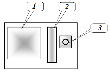
Включайте лазер только во время проведения измерений! Длина волны излучения лазера нм.
Часть 1. Линза
В данной части задачи углы отклонения луча от оптической оси считать малыми.
Расположите линзу на подставке между направляющими линейками так, чтобы она могла смещаться параллельно самой себе. Лазер закрепите в лапке штатива. На лазере закрепите картонный экран. Направьте луч лазера в центр линзы, так, чтобы отраженный луч был виден на экране и отражался приблизительно в обратном направлении. При смещении линзы вдоль направляющих отраженное пятно перемещается по экрану. Пятно получается размытым, поэтому при измерениях находите середину этого пятна.
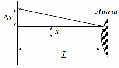
1.1 Для обеих поверхностей линзы измерьте зависимость смещения отраженного луча на экране от смещения линзы . Постройте графики полученных зависимостей.
1.2 Используя полученные данные, определите радиусы кривизны и обеих поверхностей линзы.
1.3 Расположите экран на некотором расстоянии за линзой. Измерьте зависимость смещения преломленного луча на экране от смещения линзы . Постройте график полученной зависимости.
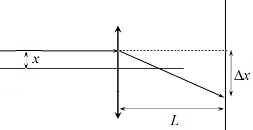
1.4 Используя полученные экспериментальные данные, определите фокусное расстояние линзы .
1.5 Рассчитайте показатель преломления материала линзы . Оцените погрешность измерения показателя преломления.
Подсказка: Вы можете использовать следующую формулу для фокусного расстояния собирающей линзы
В дальнейших частях задачи вычисление погрешностей не требуется!
Часть 2. Зеркало Френеля
Прикрепите с помощью куска пластилина пластиковую полоску с оптическими элементами на линзу, то есть используйте линзу лишь как подставку.
Расположите полученное устройство между направляющими так, чтобы луч лазера попадал на зеркало Френеля 1. Лазер с экраном расположите на расстоянии 15-20 см от зеркала. Тщательно отъюстируйте установку, так чтобы при смещении зеркала луч лазера двигался вдоль диаметра зеркала. На экране должно наблюдаться размытое отраженное пятно, которое при смещении зеркала должно двигаться практически горизонтально и на уровне выходящего из лазера луча.
Зеркало Френеля представляет собой систему концентрических колец, радиусы которых зависят от номера , отсчитываемого от центра, по закону
В этой части работы углы отклонения нельзя считать малыми.
2.1 Измерьте зависимость смещения середины отраженного пятна от смещения зеркала . Постройте график зависимости синуса угла отражения от смещения зеркала.
2.2 Оцените показатель степени в формуле (1).
Часть 3. Блестящая полоска
Направьте луч лазера на блестящую полоску 2. На экране можно увидеть несколько отраженных лучей.
3.1 Предложите такую структуру отражающей полоски, чтобы она объясняла наблюдаемую картину отраженных лучей. Определите численные значения параметров этой структуры.
Часть 4. Пластиковый преломляющий элемент
Направьте луч лазера на отверстие, закрытое пластиковым оранжевым элементом. Этот элемент имеет объемную структуру. За этим элементом расположите экран, на котором в проходящем свете можно увидеть ряд ярких пятен.
4.1 Предложите такую структуру этого оптического элемента, которая бы объясняла наблюдаемую картину прошедших лучей.
4.2 Оцените показатель преломления материала, из которого изготовлен этот оптический элемент.
Trucchi pubblicitari [15 punti]
Prova sperimentale — 16 gennaio 2013. La prova sperimentale consiste in un unico problema e dura 3 ore.
Attrezzatura: laser, sostegno con morsetto, lente convergente su supporto, schermo di cartone, carta millimetrata, due righelli di guida, righello graduato, piastrina con tre elementi ottici:
- Specchio di Fresnel (un pezzo quadrato di foglio metallico con anelli incisi);
- Striscia riflettente lucida;
- Elemento di rifrazione in plastica (un pezzetto arancione che copre un foro).
Accendete il laser soltanto durante le misurazioni!
La lunghezza d’onda dell’emissione del laser è nm.
Parte 1. La lente
In questa parte del problema, gli angoli di deviazione del raggio rispetto all’asse ottico si considerano piccoli.
Posizionate la lente su un supporto, tra i righelli di guida, in modo che possa spostarsi parallelamente a se stessa. Fissate il laser nel morsetto del sostegno e fissate sul laser lo schermo di cartone. Dirigete il raggio laser verso il centro della lente in modo che il raggio riflesso venga visualizzato sullo schermo e si diriga approssimativamente nella direzione opposta. Quando spostate la lente lungo i righelli di guida, la macchia riflessa si sposta sullo schermo. La macchia è sfocata, perciò nelle misure individuatene il centro.
1.1 Per entrambe le superfici della lente, misurare la dipendenza dello spostamento del raggio riflesso sullo schermo dallo spostamento della lente . Tracciare i grafici delle relazioni ottenute.
1.2 Utilizzando i dati raccolti, determinare i raggi di curvatura e di entrambe le superfici della lente.
1.3 Posizionare lo schermo a una certa distanza dietro la lente. Misurare la dipendenza dello spostamento del raggio rifratto sullo schermo dallo spostamento della lente . Tracciare il grafico della relazione ottenuta.
1.4 Utilizzando i dati sperimentali ottenuti, determinare la distanza focale della lente.
1.5 Calcolare il indice di rifrazione del materiale della lente . Stimare l’incertezza di misura del indice di rifrazione.
Suggerimento: È possibile utilizzare la seguente formula per calcolare la distanza focale di una lente convergente.
Nelle parti successive del problema non è necessario calcolare gli errori!
Parte 2. Specchio di Fresnel
Utilizzando un pezzo di plastilina, fissate una striscia di plastica con elementi ottici sulla lente, cioè utilizzate la lente soltanto come supporto.
Posizionate il dispositivo ottenuto tra i righelli di guida in modo che il raggio laser colpisca lo specchio di Fresnel 1. Posizionate il laser con lo schermo a una distanza di 15–20 cm dallo specchio. Allineate con cura l’apparato in modo che, spostando lo specchio, il raggio laser si muova lungo il diametro dello stesso. Sullo schermo si deve osservare una macchia riflessa sfocata che, quando lo specchio viene spostato, si muova quasi orizzontalmente e allo stesso livello del raggio laser.
Lo specchio di Fresnel è costituito da un insieme di anelli concentrici i cui raggi dipendono dal numero , conteggiato a partire dal centro, secondo la legge
In questa parte del lavoro, gli angoli di deviazione non possono essere considerati piccoli.
2.1 Misurate la dipendenza dello spostamento del centro della macchia riflessa dallo spostamento dello specchio . Tracciate un grafico che mostri la relazione tra il seno dell’angolo di riflessione e lo spostamento dello specchio.
2.2 Stimate l’esponente nella formula (1).
Parte 3. La striscia lucida
Dirigete un raggio laser verso la striscia lucida 2. Sullo schermo sarà possibile osservare diversi raggi riflessi.
3.1 Proponete una struttura della striscia riflettente in grado di spiegare il fenomeno osservato. Determinate i valori numerici dei parametri di questa struttura.
Parte 4. L’elemento ottico di rifrazione in plastica
Dirigete un raggio laser verso un foro chiuso da un elemento ottico arancione in plastica. Questo elemento presenta una struttura tridimensionale. Posizionate uno schermo dietro di esso; nella luce che lo attraversa sarà possibile osservare una serie di macchie luminose.
4.1 Proponete una struttura di questo elemento ottico in grado di spiegare il fenomeno osservato.
4.2 Stimate l’indice di rifrazione del materiale da cui è fatto questo elemento ottico.
Advertising Tricks [15 points]
Experimental competition — 16 January 2013. The experimental competition consists of one problem and lasts 3 hours.
Equipment: Laser, a stand with a clamp, a converging lens on a holder, a cardboard screen, graph paper, two guide rulers, a measuring ruler, and a plate with three optical components:
- Fresnel mirror (a square piece of foil with concentric rings);
- A shiny reflective strip;
- A plastic refracting element (an orange piece that covers an opening).
Turn on the laser only during the measurement process! The wavelength of the laser radiation is nm.
Part 1: The Lens
In this part of the task, the angles of deviation of the light beam from the optical axis are considered small.
Place the lens on its holder between the guide rulers so that it can move parallel to itself. Fix the laser in the clamp of the stand. Attach a cardboard screen to the laser. Aim the laser beam at the center of the lens so that the reflected beam is visible on the screen and travels approximately in the opposite direction. When you move the lens along the guide rulers, the reflected spot will move across the screen. Since the spot becomes blurred, determine its center during the measurements.
1.1 For both surfaces of the lens, measure the relationship between the displacement of the reflected ray on the screen and the displacement of the lens. Plot the graphs of these relationships.
1.2 Using the obtained data, determine the radii of curvature and of both surfaces of the lens.
1.3 Place the screen at a certain distance behind the lens. Measure the relationship between the displacement of the refracted ray on the screen and the displacement of the lens. Plot the graph of this relationship.
1.4 Using the experimental data obtained, determine the focal length of the lens.
1.5 Calculate the refractive index of the material from which the lens is made. Estimate the uncertainty in the measurement of the refractive index.
Hint: You can use the following formula to calculate the focal length of a converging lens.
In subsequent parts of this problem, it is not necessary to calculate the errors!
Part 2. Fresnel Mirror
Use a piece of plasticine to attach the plastic strip with optical elements to the lens, meaning use the lens merely as a holder.
Place the resulting device between the guide rulers so that the laser beam hits the Fresnel mirror 1. Position the laser with its screen 15–20 cm away from the mirror. Carefully adjust the setup so that when the mirror is moved, the laser beam moves along the diameter of the mirror. On the screen, a blurred reflected spot should appear; this spot should move almost horizontally and at the same level as the laser beam.
The Fresnel mirror consists of a system of concentric rings, the radii of which depend on the ring number , counted from the centre, according to the law
In this part of the task, the angles of deviation cannot be considered small.
2.1 Measure the dependence of the displacement of the center of the reflected spot on the displacement of the mirror. Plot a graph showing the relationship between the sine of the reflection angle and the mirror’s displacement.
2.2 Estimate the exponent in equation (1).
Part 3. The Reflective Strip
Direct a laser beam at the reflective strip 2. On the screen, several reflected beams will be observed.
3.1 Propose a structure for this reflective strip that can explain the observed pattern of reflected beams. Determine the numerical values of the parameters of this structure.
Part 4. The Plastic Refracting Element
Direct a laser beam at a hole covered by a plastic orange element. This element has a three-dimensional structure. Place a screen behind it; in the transmitted light, a series of bright spots will be visible.
4.1 Propose a structure for this optical element that can explain the observed pattern of transmitted beams.
4.2 Estimate the refractive index of the material from which this optical element is made.