Resistance of graphite (15 points)
Experimental competition — 14 January 2015. The experimental competition consists of one problem and lasts 3 hours.
Instruments and equipment: graphite rod, multimeter, power source (battery 4.5 V), fixed resistors 1.0 Ohm and 10 Ohm, variable resistor (use the sharp edge of the plastic ruler for its adjustment), connecting wires, stopwatch, vessel with snow.
Warning! Be careful, since the graphite rod is very fragile and may be easily broken. Connect it to a circuit with the clips called the “crocodile”.
Graphite electrical resistance depends on its temperature. One can approximate that this dependence is linear
wherein denotes the temperature difference between the room and the rod, is the resistance of the graphite rod at room temperature, stands for the temperature coefficient of graphite resistance.
The room temperature will be announced during the experimental competition.
It can also be assumed that the power of the heat dissipated into the ambient air is proportional to the temperature difference between the rod and the air
where is the heat transfer coefficient.
Part 1. The current-voltage characteristic of a graphite rod
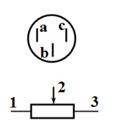
1.1 Use the multimeter (in this paragraph, use it in the mode of resistance measurements) to determine which of its pins corresponds to the sliding lead (indicated in the figure by 2).
1.2 Measure the dependence of the current through the graphite rod, which is placed in the air, on the voltage across it.
For the measurements, use the multimeter in the mode of voltmeter since it works very unstable in the mode of ammeter. To measure current, use the resistor of 1.0 ohms. To change the current in a circuit use the variable resistor. Bear in mind that when the current flows through the rod it takes some time for the temperature to change. After changing the value of the variable resistor by turning its knob, you should wait at least 30-40 seconds before taking the readings.
1.2.1 Draw schematically an electrical circuit that you used for taking measurements.
1.2.2 Plot the graph of the dependence obtained. Derive a theoretical formula that describes this dependence.
1.2.3 Calculate the electric resistivity of graphite at room temperature. Estimate its experimental error. The relative error of each resistor is 5%. The rod diameter is . To measure the length the graph paper may be used.
1.2.4 Show theoretically that in the steady state the electrical resistance of the graphite rod depends linearly on the power released in it due to the current flow
1.2.5 Using the obtained experimental data, calculate the dependence of the resistance of the graphite rod on the power . Plot the corresponding graph.
1.2.6 Using the corresponding graph write down a range of powers for which formula (1) holds. Evaluate the value of for this particular range. Error estimation is not required.
1.3 Measure the dependence of the current through the graphite rod on the voltage across it , when the rod is immersed into the melting snow.
1.3.1 Plot the graph of the obtained dependence.
1.3.2 Evaluate the temperature coefficient of graphite resistance and estimate its experimental error .
Part 2. Cooling of the graphite rod
To measure small changes in resistance it is preferable to use a bridge circuit (see. Fig.). One of the wires connected to the battery can be placed in two positions: 1 – measurement mode; 2 – heating mode.
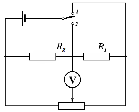
By turning the knob of the variable resistor, it can be ensured that the voltage across the voltmeter is equal to zero (or close to it). In this case the bridge is called balanced. Take resistor of 10 ohms as a resistor .
If you change the resistance of the graphite rod, the voltage across the voltmeter turns non zero. In this case it can be shown independently (you do not need to do that), that the voltage across the voltmeter is proportional to the change in the resistance of the graphite rod.
2.1 Without heating the rod, place the battery wire in the measurement mode (position 1). Use the knob of the variable resistor to make the multimeter readings close to zero (as close as possible).
Quickly switch the same battery wire in position 2, heat the rod by waiting for at least 1 minute. Then quickly switch the battery wire back in position 1 and measure the dependence of voltage on time.
2.2 Plot the dependence obtained.
2.3 If the rod is connected to a DC voltage source, but its temperature differs from the stationary one , then the change of temperature over time is approximately governed by the equation
Using the experimental data verify the validity of this equation. Calculate the value of the characteristic time of thermal equilibration. Error estimation is not required.
Resistenza della grafite (15 punti)
Prova sperimentale — 14 gennaio 2015. La prova sperimentale consiste in un unico problema e dura 3 ore.
Strumenti ed attrezzature: bacchetta di grafite, multimetro, fonte di alimentazione (batteria da 4,5 V), resistori fissi da 1,0 Ohm e 10 Ohm, resistore variabile (utilizzare il bordo affilato della riga di plastica per regolarlo), cavi di collegamento, cronometro, contenitore con neve.
Attenzione! Fate attenzione, poiché la bacchetta di grafite è molto fragile e può rompersi facilmente. Collegatela al circuito utilizzando i morsetti chiamati “coccodrilli”.
La resistenza elettrica della grafite dipende dalla sua temperatura. Si può approssimare che questa dipendenza sia lineare
dove indica la differenza di temperatura tra la stanza e la bacchetta, è la resistenza della bacchetta di grafite a temperatura ambiente, rappresenta il coefficiente di temperatura della resistenza della grafite.
La temperatura ambiente verrà annunciata durante la prova sperimentale.
Si può inoltre assumere che la potenza termica dispersa nell’aria circostante sia proporzionale alla differenza di temperatura tra la bacchetta e l’aria
dove è il coefficiente di scambio termico.
Parte 1. La caratteristica corrente-tensione di un bacchetta di grafite
1.1 Utilizzare il multimetro (in questo paragrafo, utilizzarlo in modalità di misurazione della resistenza) per determinare quale dei suoi pin corrisponde al contatto strisciante (cursore) (indicato nella figura con il numero 2).
1.2 Misurare la dipendenza della corrente che attraversa la bacchetta di grafite, posta in aria, dalla tensione applicata ai suoi estremi.
Per le misurazioni, utilizzare il multimetro in modalità di voltmetro, poiché funziona in modo molto instabile in modalità di amperometro. Per misurare la corrente, utilizzare il resistore da 1,0 ohm; per modificare il valore della corrente nel circuito, utilizzare il resistore variabile. Tenere presente che, quando la corrente attraversa la bacchetta di grafite, occorre del tempo affinché la sua temperatura cambi. Dopo aver modificato il valore del resistore variabile girando la manopola, è necessario attendere almeno 30–40 secondi prima di effettuare le misurazioni.
1.2.1 Disegnare schematicamente il circuito elettrico utilizzato per le misurazioni.
1.2.2 Tracciare il grafico che rappresenta la dipendenza osservata tra corrente e tensione. Derivare una formula teorica che descriva questa relazione.
1.2.3 Calcolare la resistività elettrica della grafite a temperatura ambiente. Stimarne l’errore sperimentale. L’errore relativo di ciascun resistore è del 5%. Il diametro della bacchetta di grafite è . Per misurare la sua lunghezza, si può utilizzare carta millimetrata.
1.2.4 Dimostrare teoricamente che, in regime stazionario, la resistenza elettrica della bacchetta di grafite dipende linearmente dalla potenza generata al suo interno per il passaggio della corrente
1.2.5 Utilizzando i dati sperimentali ottenuti, calcolare la dipendenza della resistenza del bacchetta di grafite dalla potenza . Tracciare il relativo grafico.
1.2.6 Sulla base del grafico ottenuto, indicare l’intervallo di potenze per cui vale la formula (1). Stimare il valore di in questo intervallo specifico. Non è richiesta la stima dell’errore.
1.3 Misurare la dipendenza della corrente che attraversa il bacchetta di grafite dalla tensione applicata , quando la bacchetta è immersa nella neve che fonde.
1.3.1 Tracciare il grafico della relativa dipendenza.
1.3.2 Stimare il coefficiente di temperatura della resistenza della grafite e stimare il suo errore sperimentale .
Parte 2. Raffreddamento del bacchetta di grafite
Per misurare piccole variazioni nella resistenza, è preferibile utilizzare un circuito a ponte (vedi figura). Uno dei fili collegati alla batteria può essere posizionato in due modalità: 1 – modalità di misurazione; 2 – modalità di riscaldamento.
Ruotando la manopola del resistore variabile, è possibile far sì che la tensione ai capi del voltmetro sia uguale a zero (o comunque molto vicina a zero). In questo caso, il ponte elettrico si dice “in equilibrio”. Si consideri come resistore un resistore da 10 ohm.
Se si modifica la resistenza del bacchetta di grafite (), la tensione ai capi del voltmetro diventa diversa da zero. In questo caso, si può dimostrare indipendentemente (non è necessario farlo) che la tensione ai capi del voltmetro è proporzionale alla variazione di resistenza del bacchetta di grafite.
2.1 Senza riscaldare la bacchetta, posizionare il cavo della batteria nella modalità di misurazione (posizione 1). Utilizzare la manopola del resistore variabile per far sì che i valori letti dal multimetro siano il più vicini possibile a zero.
Cambiare rapidamente il cavo della batteria nella posizione 2, riscaldare la bacchetta per almeno 1 minuto. Successivamente, riportare rapidamente il cavo nella posizione 1 e misurare la dipendenza della tensione dal tempo.
2.2 Tracciare il grafico che rappresenta questa dipendenza.
2.3 Se la bacchetta è collegata a una sorgente di tensione continua, ma la sua temperatura differisce da quella stazionaria , allora la variazione di temperatura nel tempo è approssimativamente regolata dall’equazione
Utilizzando i dati sperimentali, verificare la validità di questa equazione. Calcolare il valore del tempo caratteristico di termalizzazione. Non è richiesta la stima dell’errore.