Torsion pendulum (15.0 points)
Experimental competition — 15 January 2017 (XIII IZhO). The experimental competition consists of one problem and lasts 3 hours.
Instruments and equipment: two bolts and coupling nut, tripod with two holders or ring holders, thread, 2 wooden ruler of the length of 40 cm each, stopwatch, weight of 100 g, clay.
The torsion pendulum is two bolts rigidly joined by the nut and suspended on two threads. Make sure that the pendulum makes only torsional oscillations in a horizontal plane. The free fall acceleration due to gravity is .
Part 1. Free small oscillations (5.0 points)
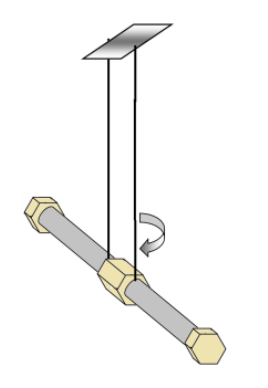
1.1 Measure dependence of the period of small torsional oscillations of the pendulum on the length of threads in the range from 10 to 50 cm.
1.2 Derive the theoretical formula for the period of small torsional oscillations.
1.3 Prove graphically that the derived formula correctly describes the experimental data.
1.4 Calculate the radius of gyration of the pendulum and evaluate the experimental error.
Hint: The moment of inertia of a rigid body about a certain axis may be represented in the form , where is the body mass and stands for the radius of gyration.
In all following parts error analysis is not required!
Part 2. Small oscillations with additional tension (5.0 points)
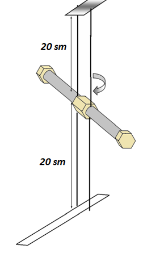
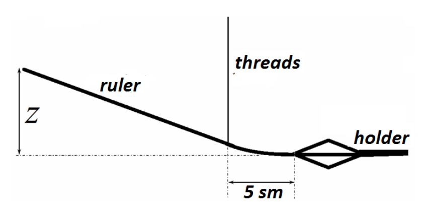
Tie another two threads from below the bolts. They must also be parallel and located at the same distance as the two upper threads. At the bottom tie them to a wooden ruler of length 40 cm. To do this, fix the ruler tight in the tripod holder. You can also place the ruler under the tripod platform. The threads must be tied to the ruler at a distance of 4-5 cm from the holder. The lengths of the threads at the top and bottom of the bolts must be the same and equal to about 20 cm. By raising or lowering the upper tripod holder, you can change the tension of the threads. Tension of threads is measured by the magnitude of the ruler bending, as shown in the figure below.
2.1 Measure the dependence of the period of small torsional oscillations on the threads tension, i.e. on the ruler bending .
2.2 Derive the theoretical dependence of the oscillation period on the threads tension.
2.3 Present the experimental data on the graph in such a way that it confirms the derived theoretical dependence.
Part 3. Twisting at large angles (5.0 points)
In this part the pendulum should be twisted at large angles, which are measured by the number of half-turns . The measurements should be carried out with a chosen moderate thread tension that you should exactly state.
3.1 Study the dependence of the time of the pendulum untwisting on the initial twisting angle . Plot the graph of the resulting dependence.
3.2 It can be approximately assumed that the potential energy of elastic deformation depends on the twisting angle as
where is a constant. Based on the experimental data, decide which range the exponent falls in: a) ; b) ; c) .
If the pendulum is initially twisted to a certain angle , the pendulum unwinds such that the threads turn in parallel again, and then due to inertia the pendulum is re-twisted to some smaller angle .
3.3 Study the dependence of the re-twisting angle on the initial twisting angle . The measurements must be taken at two different magnitudes of the threads tension (but you should state them). Plot the graphs of the obtained dependencies. Propose a simple formula to describe the resulting dependence. Evaluate the numerical values of the parameters in your dependence.
Adjusting the threads tension during torsional oscillations of the pendulum can provide some intake of energy. Place the tripod with the pendulum at the edge of the table. At the bottom the thread should cover the ruler, fixed in the holder or under the tripod platform. Suspend the weight of 100 g to the thread below the ruler.
3.4 Study the dependence of the re-twisting angle on the initial twisting angle in this case. Plot the graph of the obtained dependence. Propose a simple formula to describe the resulting dependence. Evaluate the numerical values of the parameters in your dependence.
3.5 Repeat the experiment described in section 3.4, but lift the suspended weight up at the stage of re-twisting and do not touch the weight at the stage of untwisting. Study the dependence of the re-twisting angle on the initial twisting angle in this case. Plot the graph of the obtained dependence in the same graph as in section 3.4. Propose a simple formula to describe the resulting dependence. Evaluate the numerical values of the parameters in your dependence.
Pendolo di torsione (15,0 punti)
Competizione sperimentale – 15 gennaio 2017 (XIII IZhO). La competizione sperimentale consiste in un unico problema e dura 3 ore.
Strumenti ed attrezzature: due bulloni e un dado di accoppiamento, treppiede con due morsetti o supporti ad anello, filo, 2 righe di legno lunghe ciascuna 40 cm, cronometro, un peso da 100 g, argilla.
Il pendolo di torsione è costituito da due bulloni collegati rigidamente dal dado e sospesi a due fili. Assicurarsi che il pendolo esegua soltanto oscillazioni di torsione in un piano orizzontale. L’accelerazione di caduta libera dovuta alla gravità è .
Parte 1. Piccole oscillazioni libere (5,0 punti)
1.1 Misurare la dipendenza del periodo delle piccole oscillazioni torsionali del pendolo dalla lunghezza dei fili, nell’intervallo da 10 a 50 cm.
1.2 Ricavare la formula teorica per il periodo delle piccole oscillazioni torsionali.
1.3 Dimostrare graficamente che la formula ricavata descrive correttamente i dati sperimentali.
1.4 Calcolare il raggio d’inerzia del pendolo e valutare l’errore sperimentale.
Suggerimento: Il momento d’inerzia di un corpo rigido rispetto a un certo asse può essere espresso nella forma , dove è la massa del corpo e rappresenta il raggio d’inerzia.
In tutte le parti successive non è richiesta l’analisi dell’errore!
Parte 2. Piccole oscillazioni con tensione aggiuntiva (5,0 punti)
Legare altri due fili sotto i bulloni; anch’essi devono essere paralleli e posti alla stessa distanza dei due fili superiori. In basso, legare questi fili a una riga di legno lunga 40 cm, fissandola saldamente nel supporto del treppiede. È anche possibile posizionare la riga sotto la piattaforma del treppiede; i fili devono essere legati alla riga a una distanza di circa 4-5 cm dal supporto. La lunghezza dei fili sia in alto che in basso sui bulloni deve essere uguale, circa 20 cm. Alzando o abbassando il supporto superiore del treppiede, è possibile modificare la tensione dei fili. La tensione dei fili si misura in base all’entità della flessione della riga, indicata con la variabile , come mostrato nella figura sottostante.
2.1 Misurare la dipendenza del periodo delle piccole oscillazioni torsionali dalla tensione dei fili, cioè dalla flessione della riga.
2.2 Ricavare la relazione teorica tra il periodo delle oscillazioni e la tensione dei fili.
2.3 Presentare i dati sperimentali su un grafico in modo che confermino la relazione teorica ricavata.
Parte 3. Torsione ad angoli grandi (5,0 punti)
In questa parte, il pendolo deve essere torto ad angoli grandi, misurati in numero di mezzi giri . Le misurazioni devono essere effettuate utilizzando una tensione del filo moderata, da specificare con precisione.
3.1 Studiare la dipendenza del tempo necessario al pendolo per svolgersi dall’angolo di torsione iniziale . Tracciare il grafico che rappresenti questa relazione.
3.2 Si può assumere approssimativamente che l’energia potenziale derivante dalla deformazione elastica dipenda dall’angolo di torsione come
dove è una costante. Sulla base dei dati sperimentali, stabilire in quale intervallo rientra l’esponente : a) ; b) ; c) .
Se il pendolo viene inizialmente torto di un certo angolo , si svolge finché i fili tornano paralleli e poi, per inerzia, si ritorce di un angolo più piccolo .
3.3 Studiare la dipendenza dell’angolo di ritorsione dall’angolo di torsione iniziale . Le misurazioni devono essere effettuate con due diverse tensioni dei fili (che vanno indicate esplicitamente). Tracciare i grafici delle relazioni ottenute e proporre una formula semplice per descriverle. Calcolare i valori numerici dei parametri in queste relazioni.
Regolando la tensione dei fili durante le oscillazioni torsionali del pendolo si può fornire energia al sistema. Posizionare il treppiede con il pendolo sul bordo di un tavolo; alla base, il filo deve passare sopra la riga fissata in un supporto o sotto la piattaforma del treppiede. Sospendere un peso di 100 g al filo, sotto la riga.
3.4 Studiare in questo caso la dipendenza dell’angolo di ritorsione dall’angolo di torsione iniziale . Tracciare il grafico della relazione ottenuta e proporre una formula semplice per descriverla. Calcolare i valori numerici dei parametri in queste relazioni.
3.5 Ripetere l’esperimento descritto nella sezione 3.4, ma sollevare il peso sospeso durante la fase di ritorsione e non toccarlo durante la fase di svolgimento. Studiare in questo caso la dipendenza dell’angolo di ritorsione dall’angolo di torsione iniziale . Tracciare il grafico della relazione ottenuta nello stesso grafico utilizzato nella sezione 3.4. Proporre una formula semplice per descrivere questa dipendenza. Calcolare i valori numerici dei parametri che caratterizzano tale relazione.