Absorption of light (15.0 points)
Experimental competition — 12 January 2019 (XV IZhO). The experimental competition consists of one problem and lasts 3 hours.
Experimental equipment
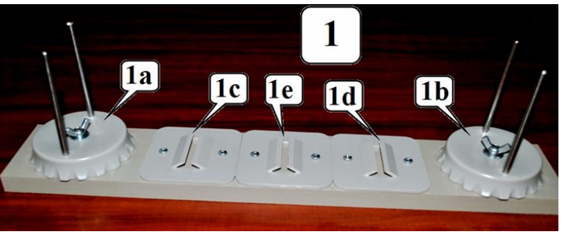
- Optical bench with holders:
- 1a – support for a light source with the screw;
- 1b – support for a photodetector with the screw;
- 1c, 1d, 1e – holders;
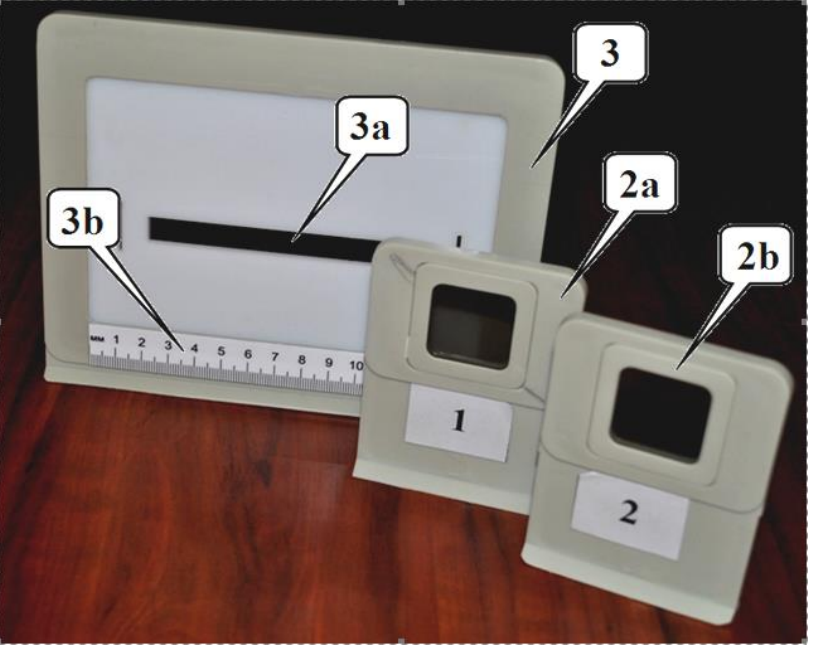
- 2a – neutral filter on the stand;
- 2b, 3, 3a, 3b – not used in this experiment;
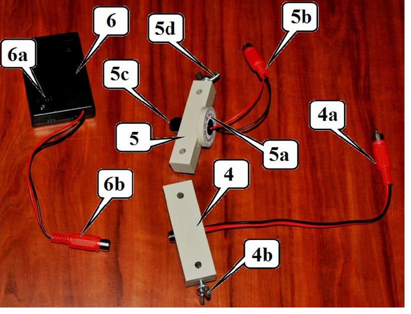
Light sources:
- 4 – light emitting diode (LED): 4a – leads to a power supply; 4b – fixing screw;
- 5 – laser: 5a – ring for turning the laser with the scale; 5b – leads to a power supply; 5c – screw for the beam width adjustment on the front side; 5d – fixing screw;
- 6 – power supply for light sources: 6a – switch; 6b – leads to a light source.
Keep the source operating only while making measurements! Do not point the laser beam in your or anyone’s eyes, it is very dangerous!
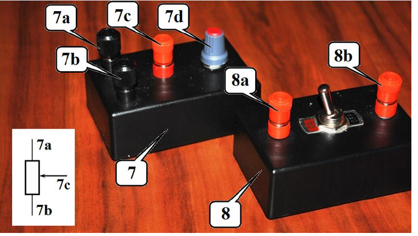
- 7 – variable resistor 100 kΩ: 7a, 7b, 7c – terminals for connection to a circuit; 7d – knob for changing the resistance;
- 8 – switch: 8a, 8b – terminals for connection to a circuit;
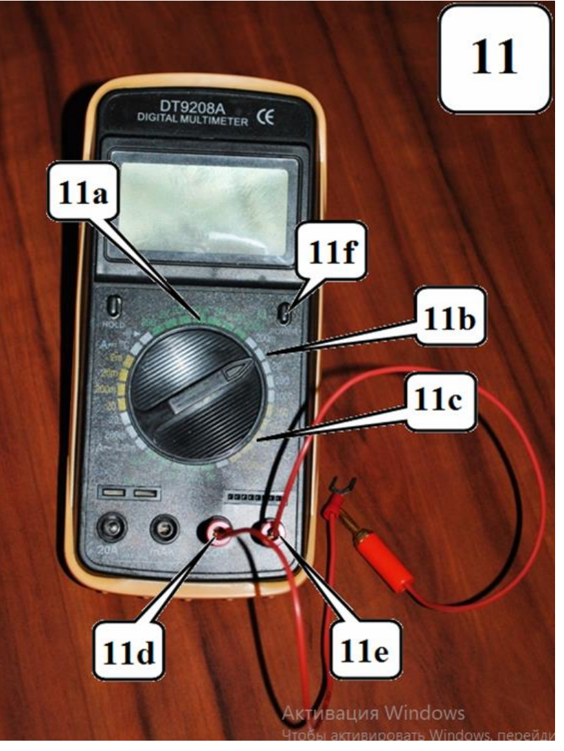
- 11 – multimeter: 11a – register to measure resistance (100 kΩ); 11b – register to measure DC voltage (2V); 11d, 11e – connectors for test leads; 11f – power on/off.
If the display multimeter is in a “sleep” mode - double-press power on/off! When measuring the resistance with the multimeter, it must be disconnected with a power supply!
A set of film filters: 5 grey filters, 5 blue filters, 5 yellow filters. Clothes-peg.
Part 1. Studying a photodetector
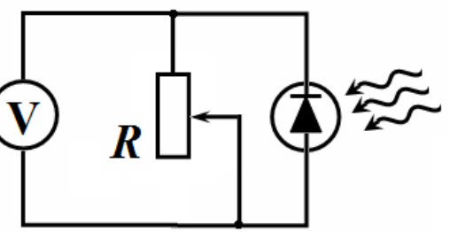
To measure the light intensity the photodiode is used hereinafter. The emf, produced when the light falls on the photodiode, depends in a complex way on the intensity of the incident light. Therefore, the circuit, shown in the figure, is used to measure the light intensity. The voltage measured by a multimeter depends on both the intensity of the incident light and the resistance of the variable resistor.
Install the photodetector and the laser on the optical bench. Direct the light beam exactly at the photodetector. Install a neutral filter in one of the holders. Rotating the laser ring, make sure that the voltage across the resistor (at its maximum resistance) is at least 350 mV.
1.1 Modify the circuit shown above by adding the switch, so that you can measure the resistance of the resistor and the voltage across it with the single multimeter provided. Draw schematically the electric circuit that you propose.
1.2 Using your electric circuit from 1.1, measure the dependence of the voltage across the resistor on its resistance.
1.3 Using the data from 1.2, draw a graph of the voltage across the resistor as a function of its current.
1.4 Draw a graph of the heat power generated in the resistor as a function of its resistance.
1.5 Determine the resistance of the resistor at which the heat power turns maximal. Make additional measurements, if necessary.
Part 2. Absorption of laser radiation
In this part of the experiment, make all measurements with the resistance of the variable resistor approximately equal to 3 kΩ. Write down the value of the resistance at which you have taken your measurements. Install the neutral filter on the optical bench between the laser and the photodetector. Turning the laser ring, make sure that the maximum voltage across the resistor is approximately 180-190 mV. Measure in the range of the multimeter 200mV. In this mode, the voltage on the multimeter is directly proportional to the intensity of the incident light. Hold the light filters with the clothes-peg and hold them directly near the photodetector.
The intensity of the light transmitted through the filter is proportional to the intensity of the incident light :
The transmittance does not depend on the intensity of the incident light but may depend on its wavelength.
2.1 Using formula (1), obtain the dependence of the intensity of transmitted light through identical light filters on the number of light filters.
2.2 Measure the dependence of the light intensity on the number of filters for all the filters provided (gray, yellow and blue). Draw graphs of the dependencies obtained in scales that allow you to verify the formula obtained in Section 2.1.
2.3 Calculate the transmittance of all filters. Estimate the experimental errors of their values.
2.4 Measure the transmittance for pairs of different filters: gray + blue, gray + yellow; blue + yellow. Theoretically calculate the transmittance of each pair of filters.
Part 3. Absorption of white light
Replace the laser with the LED which is a source of white light. Remove the neutral filter. Direct the radiation of the LED straight at the photodetector. Set the resistance of the resistor to approximately 10 kΩ. Write down the value of the resistance at which you have taken your measurements.
3.1 Measure the dependence of the light intensity on the number of filters for all types of filters provided (gray, yellow and blue). Draw graphs of these dependencies in the same scale as in Part 2.
3.2 Verify whether the formula obtained in paragraph 2.1 is fulfilled for the white light source. Specify a main cause leading to possible violations of that relation.
3.3 Measure the transmittance for pairs of different filters: gray + blue, gray + yellow; blue + yellow. Using the data obtained in the whole experiment, verify whether the transmittance of a pair of filters is equal to the product of the transmittances of each filter.
Assorbimento della luce (15,0 punti)
Competizione sperimentale – 12 gennaio 2019 (XV IZhO). La competizione sperimentale consiste in un unico problema e dura 3 ore.
Attrezzatura sperimentale
- Banco ottico con supporti:
- 1a – Supporto per una sorgente di luce, con vite;
- 1b – Supporto per un fotodetettore, con vite;
- 1c, 1d, 1e – supporti;
- 2a – filtro neutro sul supporto;
- 2b, 3, 3a, 3b – non utilizzati in questo esperimento.
Sorgenti di luce:
- 4 – Diodo emettitore di luce (LED): 4a – connessioni per l’alimentazione; 4b – vite di fissaggio;
- 5 – Laser: 5a – anello con scala per ruotare il laser; 5b – connessioni per l’alimentazione; 5c – vite per regolare la larghezza del raggio sul lato anteriore; 5d – vite di fissaggio;
- 6 – Alimentatore delle sorgenti di luce: 6a – interruttore; 6b – connessioni alla sorgente di luce.
Tenere la sorgente accesa solo durante le misurazioni! Non puntare il raggio laser verso i propri occhi o quelli di chiunque: è estremamente pericoloso!
- 7 – Resistore variabile da 100 kΩ: 7a, 7b, 7c – Terminali per la connessione in un circuito; 7d – Manopola per modificare la resistenza;
- 8 – Interruttore: 8a, 8b – Terminali per la connessione in un circuito.
- 11 – Multimetro: 11a – posizione del selettore per misurare la resistenza (100 kΩ); 11b – posizione del selettore per misurare la tensione continua (2 V); 11d, 11e – Connettori per i cavi di prova; 11f – Interruttore per l’accensione/spegnimento.
Se lo schermo del multimetro è in modalità “sospesa”, premere due volte l’interruttore per accenderlo! Durante la misurazione della resistenza, il multimetro deve essere scollegato dall’alimentazione!
Un set di filtri a pellicola: 5 filtri grigi, 5 filtri blu, 5 filtri gialli. Molletta da bucato.
Parte 1. Studio di un fotodetettore
Per misurare l’intensità della luce, in seguito verrà utilizzato il fotodiodo. La f.e.m. prodotta quando la luce colpisce il fotodiodo dipende in modo complesso dall’intensità della luce incidente. Pertanto, viene utilizzato il circuito mostrato nella figura per misurare l’intensità della luce. La tensione misurata con un multimetro dipende sia dall’intensità della luce incidente che dalla resistenza del resistore variabile.
Installare il fotodetettore e il laser sul banco ottico. Dirigere il raggio di luce esattamente verso il fotodetettore. Inserire un filtro neutro in uno dei supporti. Ruotando l’anello del laser, assicurarsi che la tensione applicata al resistore (alla sua massima resistenza) sia almeno di 350 mV.
1.1 Modificare il circuito mostrato sopra aggiungendo un interruttore, in modo da poter misurare sia la resistenza del resistore che la tensione applicata ad esso utilizzando il solo multimetro a disposizione. Disegnare schematicamente il circuito elettrico proposto.
1.2 Utilizzando il circuito realizzato in 1.1, misurare la dipendenza della tensione applicata al resistore dalla sua resistenza.
1.3 Utilizzando i dati ottenuti in 1.2, tracciare un grafico che rappresenti la tensione applicata al resistore in funzione della corrente che attraversa lo stesso.
1.4 Tracciare un grafico che rappresenti la potenza termica generata nel resistore in funzione della sua resistenza.
1.5 Determinare la resistenza del resistore alla quale la potenza termica raggiunge il suo valore massimo. Effettuare eventuali misurazioni aggiuntive, se necessario.
Parte 2. Assorbimento della radiazione laser
In questa parte dell’esperimento, effettuare tutte le misurazioni con la resistenza del resistore variabile approssimativamente uguale a 3 kΩ. Annotare il valore della resistenza utilizzato per le misurazioni. Installare il filtro neutro sul banco ottico, tra il laser e il fotodetettore. Ruotando l’anello del laser, assicurarsi che la tensione massima applicata al resistore sia approssimativamente di 180-190 mV. Misurare sulla portata 200 mV del multimetro; in questo modo, la tensione indicata dal multimetro è direttamente proporzionale all’intensità della luce incidente. Tenere i filtri con la molletta e posizionarli direttamente vicino al fotodetettore.
L’intensità della luce che passa attraverso il filtro è proporzionale all’intensità della luce incidente :
Il coefficiente di trasmissione non dipende dall’intensità della luce incidente, ma può dipendere dalla sua lunghezza d’onda.
2.1 Utilizzando la formula (1), determinare in che modo l’intensità della luce trasmessa attraverso filtri luminosi identici varia in funzione del numero di tali filtri.
2.2 Misurare come varia l’intensità della luce in funzione del numero di filtri per tutti i filtri forniti (grigio, giallo e blu). Tracciare grafici delle relazioni ottenute su scale che permettano di verificare la formula ricavata nella Sezione 2.1.
2.3 Calcolare il coefficiente di trasmissione di tutti i filtri e stimare gli errori sperimentali dei loro valori.
2.4 Misurare il coefficiente di trasmissione per coppie di filtri diversi: grigio + blu, grigio + giallo; blu + giallo. Calcolare teoricamente il coefficiente di trasmissione di ciascuna coppia di filtri.
Parte 3. Assorbimento della luce bianca
Sostituire il laser con un LED, che è una sorgente di luce bianca. Rimuovere il filtro neutro. Dirigere il raggio emesso dal LED direttamente verso il fotodetettore. Impostare la resistenza del resistore a circa 10 kΩ. Annotare il valore della resistenza utilizzato per le misurazioni.
3.1 Misurare come varia l’intensità della luce in funzione del numero di filtri per tutti i tipi di filtri forniti (grigio, giallo e blu). Tracciare grafici di queste relazioni nella stessa scala della Parte 2.
3.2 Verificare se la formula ottenuta nel paragrafo 2.1 si applica anche alla sorgente di luce bianca. Indicare la causa principale che può portare a violazioni di tale relazione.
3.3 Misurare il coefficiente di trasmissione per coppie di filtri diversi: grigio + blu, grigio + giallo; blu + giallo. Utilizzando i dati ottenuti nell’intero esperimento, verificare se il coefficiente di trasmissione di una coppia di filtri è uguale al prodotto dei coefficienti di trasmissione dei singoli filtri.