Problem 1 (10.0 points)
Theoretical competition — January 9, 2024 (XX IZhO).
This problem consists of three independent parts.
Problem 1.1 (3.0 points)
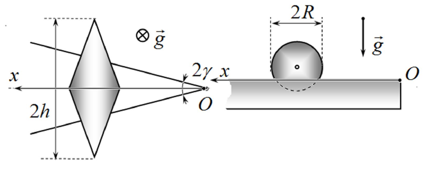
On two identical horizontal V-shaped slats (see figure below), forming a dihedral angle of (), there is a solid bicone with a base diameter of cm and a distance between the vertices of cm, representing two identical homogeneous cones, rigidly fastened by their bases. First, the bicone is held so that its center of mass is right above the vertex of the dihedral angle, symmetrically relative to its bisectoral plane. Then it is released and it begins to roll along the slats without slipping. Find the dependence of the bicone speed of translational motion of the on the coordinate measured horizontally from the vertex of the dihedral angle to the center of mass of the bicone. Calculate the speed of the bicone at cm. Determine the maximum angular velocity , that the bicone is to reach during its motion. Consider that the height of the slats exceeds the radius of the cone bases, and the acceleration of gravity is m/c².
Problem 1.2 (4.0 points)
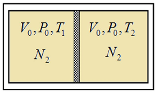
A thermally insulated vessel with a volume of l is divided by a thin weightless movable heat-conducting partition into two equal parts, each containing nitrogen at a pressure kPa. The initial temperature of nitrogen in one half of the vessel is K, and it is K in the other. As a result of heat exchange, the partition begins to move slowly without friction. 1) Determine the amount of heat that will be exchanged between parts of the vessel by the time complete thermodynamic equilibrium is established; 2) Calculate the minimum work that must be done to return the partition to its original position. Neglect the heat capacities of the vessel and partition.
Problem 1.3 (3.0 points)
An electric motor connected to a battery lifts a load of mass at a constant speed to a certain height in time min. In this case, the load is tied to a thread that is wound on a uniformly rotating electric motor shaft. The time it takes to lift two loads with a total mass of to the same height turns out to be s longer. 1) Find the maximum number of loads of the same mass that such an electric motor can lift; 2) Calculate the time that the electric motor is to require to uniformly lift the maximum number of loads to the height . Consider that the torque of an electric motor is proportional to the current flowing through its winding.
Topic: Rotational Dynamics, Thermodynamics, Circuits Metodi: Torque & Angular Momentum Analysis, Energy Conservation Method, First Law of Thermodynamics Competenze: Physical Reasoning, Mathematical Modeling
Problema 1 (10,0 punti)
Prova teorica — 9 gennaio 2024 (XX IZhO).
Questo problema è composto da tre parti indipendenti.
Problema 1.1 (3,0 punti)
Su due identiche listelli orizzontali a V (vedere la figura sottostante), che formano un angolo diedrale di (), è posizionato un bicono solido con un diametro di base pari a cm e una distanza tra i vertici di cm; tale bicono rappresenta due coni omogenei identici, fissati rigidamente per le basi. Inizialmente, il bicono viene posizionato in modo che il suo centro di massa si trovi esattamente sopra il vertice dell’angolo diedrale, in posizione simmetrica rispetto al piano della sua bisettrice. Successivamente viene rilasciato e inizia a rotolare lungo i listelli senza scivolare. Determinare la dipendenza della velocità di traslazione del bicono in funzione della coordinata , misurata orizzontalmente dal vertice dell’angolo diedrale al centro di massa del bicono. Calcolare la velocità del bicono quando cm. Determinare inoltre la massima velocità angolare che il bicono può raggiungere durante il suo movimento. Si consideri che l’altezza dei listelli supera il raggio delle basi dei coni e che l’accelerazione di gravità è m/c².
Problema 1.2 (4,0 punti)
Un contenitore termicamente isolato, con un volume di l, è diviso da una sottile parete mobile, senza peso, che conduce il calore in due parti uguali; ciascuna parte contiene azoto () a una pressione di kPa. La temperatura iniziale dell’azoto nella prima metà del contenitore è di K, mentre nell’altra metà è di K. A seguito dello scambio termico, la parete inizia a muoversi lentamente e senza attrito. 1) Determinare la quantità di calore () che verrà scambiata tra le due parti del contenitore al momento dell’instaurarsi dell’equilibrio termodinamico completo; 2) Calcolare il lavoro minimo () necessario per riportare la parete nella sua posizione iniziale. Ignorare le capacità termiche del contenitore e della parete stessa.
Problema 1.3 (3,0 punti)
Un motore elettrico collegato a una batteria solleva un carico di massa a velocità costante fino a un’altezza in tempo min. In questo caso, il carico è fissato a un filo avvolto attorno all’albero del motore che ruota uniformemente. Il tempo necessario per sollevare due carichi di massa totale fino alla stessa altezza risulta essere s più lungo. 1) Determinare il numero massimo di carichi della stessa massa che tale motore elettrico può sollevare; 2) Calcolare il tempo necessario al motore per sollevare uniformemente il numero massimo di carichi fino all’altezza . Si consideri che la coppia di un motore elettrico è proporzionale alla corrente che scorre attraverso i suoi avvolgimenti.
Problem 2. Lagrange points (10.0 points)
Two body problem
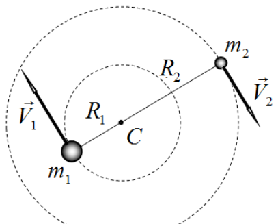
Consider the two-body problem. Two massive bodies with masses , and respectively, move only under the influence of the force of gravitational interaction in circular orbits around a common center of mass . The distance between the bodies remains unchanged and equal to .
2.1 Find the radii and of the trajectories of the bodies. Express your answer through the quantities .
2.2 Find the angular velocity of the bodies rotations. Express your answer through the quantities and the gravitational constant .
Lagrange points in a three-body system
Lagrange points, libration points (Latin librātiō – swinging) or L-points are points in the space of a system of two massive bodies in which a third body with negligible mass, not affected by any other forces other than gravitational ones from the first two, can remain motionless relative to these bodies.
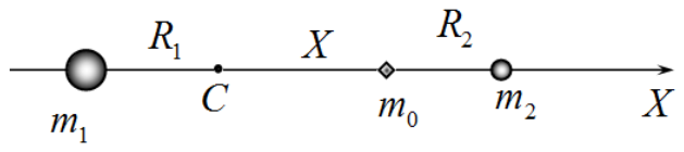
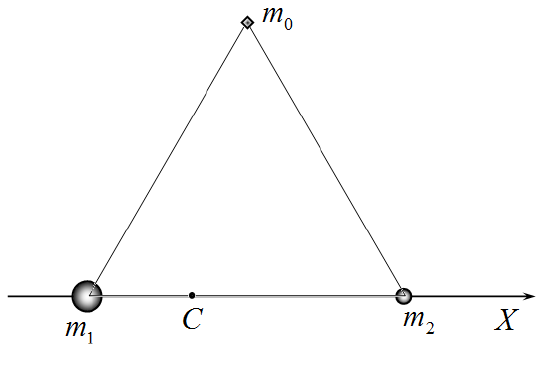
Consider adding a third body to the system described above, the mass of which is significantly less than the masses of the first two bodies, . Introduce the axis along a straight line passing through the bodies , as shown in the figure. The origin is compatible with the center of mass . To simplify mathematical transformations, use the following quantities:
- as a unit of length, use the distance between bodies ; the position of a small body is determined by the dimensionless coordinate , which can vary from minus to plus infinity;
- as a unit of force use the quantity ;
- introduce the dimensionless parameter .
2.3 Obtain an exact equation for determining the coordinates of Lagrange points lying on the axis. In addition to the desired coordinate, this equation should include only the parameter .
2.4 Draw a schematic graph of the projection onto the axis of the force acting on a small body from two massive bodies at . Express your answer in terms of relative units and .
2.5 Determine the possible number of Lagrange points that exist on the axis.
2.6 Calculate the numerical values of the coordinates of these points with an error not exceeding if .
2.7 Prove that the point lying at the vertex of a regular triangle constructed on the segment is a Lagrange point.
Lagrange points in the Solar System
For calculations, use the following numerical values of astronomical quantities: solar mass kg; Earth mass kg; the Earth’s orbit can be considered a circle with radius ; Jupiter’s orbital period around the Sun is 11.9 Earth years.
SOHO is a solar observing spacecraft, a joint project of ESA and NASA, which was launched on December 2, 1995 and began operations in May 1996. The device is located on the straight line connecting the Sun and the Earth, its position relative to the Earth remains practically unchanged over time.
2.8 Determine at what distance from the Earth the SOHO spacecraft is located. Express the formula in terms of the ratio of the masses of the Earth and the Sun and the radius of the Earth’s orbit. Calculate the numerical value of this distance.
On December 25, 2021, a spacecraft equipped with the James Webb infrared telescope was successfully launched from the Kourou spaceport using an Ariane 5 rocket. In January 2022, this device reached its permanent deployment point. The position of the telescope is to remain virtually unchanged relative to the Earth, and it is assumed to stay in the Earth shadow all the time.
2.9 Determine at what distance from the Earth the James Webb telescope is located. Express your answer in terms of the Earth-to-Sun mass ratio and the radius of the Earth’s orbit. Calculate the numerical value of this distance.
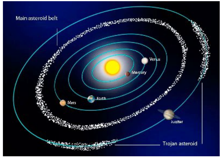
Small planets, called asteroids, are distributed extremely unevenly in the Solar System: in addition to the well-known asteroid belt, located between the orbits of Mars and Jupiter, there are two large groups of asteroids moving near the orbit of Jupiter. These groups of asteroids are called “Trojan” asteroids.
2.10 Calculate the distances from Jupiter to the centers of groups of Trojan asteroids.
Topic: Gravitation Metodi: Newton’s Law of Gravitation, Kepler’s Laws Competenze: Mathematical Modeling, Estimation & Approximation
Problema 2. Punti di Lagrange (10,0 punti)
Problema a due corpi
Si consideri il problema a due corpi. Due corpi di massa e , rispettivamente, si muovono esclusivamente sotto l’azione della forza di interazione gravitazionale, descrivendo orbite circolari attorno a un centro di massa comune . La distanza tra i due corpi rimane costante e uguale a .
2.1 Determinare i raggi e delle orbite dei due corpi. Esprimere la risposta in termini delle grandezze .
2.2 Calcolare la velocità angolare di rotazione dei due corpi. Esprimere la risposta in termini delle grandezze e della costante gravitazionale .
Punti di Lagrange in un sistema a tre corpi
I punti di Lagrange, noti anche come punti di librazione (dal latino “librātiō” – oscillazione), sono punti nello spazio di un sistema costituito da due corpi massicci nei quali un terzo corpo, la cui massa è trascurabile e che non è soggetto ad altre forze se non a quelle gravitazionali generate dai primi due, può rimanere fermo rispetto a questi ultimi.
Si consideri l’aggiunta di un terzo corpo al sistema descritto sopra, la cui massa è significativamente inferiore a quella dei primi due corpi, . Si introduca l’asse lungo una retta che passa attraverso i corpi , come mostrato nella figura. L’origine dell’asse è coincidente con il centro di massa . Per semplificare le trasformazioni matematiche, si utilizzino le seguenti grandezze:
- come unità di lunghezza, la distanza tra i corpi ; la posizione di un piccolo corpo è determinata dalla coordinata adimensionale , che può variare da meno infinito a più infinito;
- come unità di forza, la grandezza ;
- si introduca il parametro adimensionale .
2.3 Ottenere un’equazione esatta per determinare le coordinate dei punti di Lagrange situati sull’asse . Oltre alla coordinata desiderata, questa equazione deve includere soltanto il parametro .
2.4 Tracciare un grafico schematico della proiezione sull’asse della forza che agisce su un piccolo corpo da parte di due corpi massicci, per il valore di . Esprimere la risposta in termini di unità relative: e .
2.5 Determinare il numero possibile di punti di Lagrange che esistono sull’asse .
2.6 Calcolare i valori numerici delle coordinate di questi punti con un errore non superiore a , se .
2.7 Dimostrare che il punto situato all’apice di un triangolo regolare costruito sul segmento è un punto Lagrange.
Punti di Lagrange nel Sistema Solare
Per i calcoli, utilizzare i seguenti valori numerici di quantità astronomiche: massa solare kg; massa terrestre kg; l’orbita terrestre può essere considerata un cerchio con raggio ; il periodo orbitale di Giove attorno al Sole è di 11,9 anni terrestri.
SOHO è una sonda spaziale per l’osservazione del Sole, progetto congiunto di ESA e NASA, lanciata il 2 dicembre 1995 e messa in funzione nel maggio 1996. La sonda si trova sulla linea retta che collega il Sole e la Terra; la sua posizione rispetto alla Terra rimane praticamente invariata nel tempo.
2.8 Determinare a quale distanza dalla Terra si trova la sonda SOHO. Esprimere la formula in termini del rapporto tra le masse della Terra e del Sole e del raggio dell’orbita terrestre. Calcolare il valore numerico di questa distanza.
Il 25 dicembre 2021, una sonda spaziale equipaggiata con il telescopio infrarosso James Webb è stata lanciata con successo dal porto spaziale di Kourou utilizzando un razzo Ariane 5. Nel gennaio 2022, questo dispositivo ha raggiunto la sua posizione definitiva di operazione. La posizione del telescopio deve rimanere sostanzialmente invariata rispetto alla Terra, e si presuppone che rimanga costantemente all’interno dell’ombra terrestre.
2.9 Determinare a quale distanza dalla Terra si trova il telescopio James Webb. Esprimere la risposta in termini del rapporto tra la massa della Terra e quella del Sole, nonché del raggio dell’orbita terrestre. Calcolare il valore numerico di questa distanza.
I piccoli pianeti, chiamati asteroidi, sono distribuiti in modo estremamente disomogeneo nel Sistema Solare: oltre alla ben nota cintura di asteroidi, situata tra le orbite di Marte e Giove, esistono due grandi gruppi di asteroidi che si muovono vicino all’orbita di Giove. Questi gruppi di asteroidi sono chiamati “asteroidi troiani”.
2.10 Calcolare le distanze da Giove ai centri dei gruppi di asteroidi troiani.
Problem 3. Geometric optics and photodetector (10.0 points)
In this problem, the laws of geometric optics are to be studied using a photodetector, which is a device for converting light energy into electrical energy. It is assumed that the absorbing surface of the photodetector is flat and when it is connected to a milliammeter, it shows a current value proportional to the power of the absorbed electromagnetic radiation.
Geometric optics is a branch of optics that studies the laws of light propagation in transparent media, the reflection of light from mirror-reflecting surfaces, and the principles of constructing images when light passes through optical systems without taking into account its wave properties. The basic concept of geometric optics is a light beam. This implies that the direction of the flow of radiant energy (path of the light beam) does not depend on the transverse dimensions of the light beam. Let us recall the laws of geometric optics necessary for this problem solution.
3.1 When reflected from a flat surface, the incident and reflected rays lie in the same plane with the normal at the point of incidence. Let the incident ray make an angle with the normal, and the reflected ray make an angle . Write down the relationship between these angles.
3.2 When light falls from air onto a flat surface of a material with refractive index , the incident and refracted rays also lie in the same plane with the normal at the point of incidence. Let the incident ray make an angle with the normal, and the refracted ray make an angle . Write down the relationship between these angles.
In the following parts of this problem, we consider only situations in which, in the processes of light refraction, the above-mentioned angles are small and the approximation of paraxial optics holds.
3.3 Rewrite the answer to 3.2 in the case of small angles of incidence and refraction.
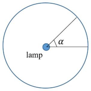
In this problem, the radiation source is assumed to be a very long, thin cylindrical lamp, the surface of which emits equally in all directions.
3.4 Let the radiation power of the lamp from its entire surface be . Determine the radiation power concentrated in a plane angle as shown in the figure.
Thin plate
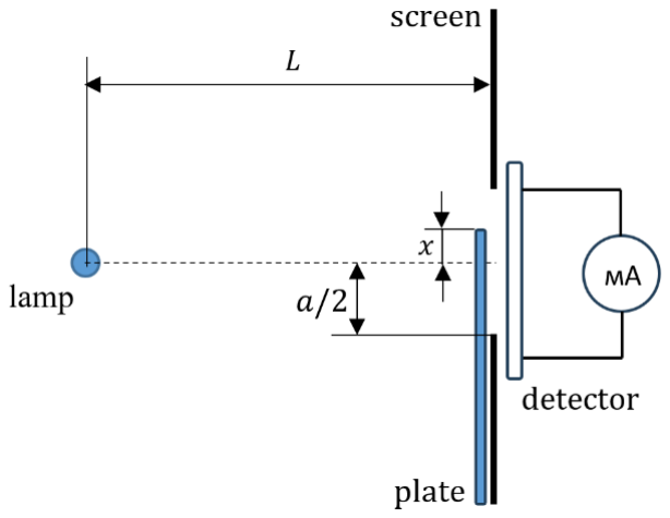
Let the light source described above illuminate an opaque screen in which a rectangular slit cm wide is made. The lamp is located parallel to the edges of the slit directly opposite its center at a distance of cm, and immediately behind the slit the surface of the photodetector is placed in such a way that it captures the entire luminous flux passing through the slit. The photodetector itself is connected to a milliammeter. A thin rectangular plate can move in parallel along the screen, the upper edge of which is parallel to the edges of the slit, while the material of the plate is translucent with a transmittance coefficient of . In the absence of the plate, the milliammeter shows the current value mA.
3.5 Let now be the coordinate from the center of the slit to the edge of the plate with the axis vertically directed upward. Plot a graph of the deviation of the milliammeter readings in milliammeteres from the initial reading from the coordinate in the range of cm to cm. Explicitly indicate the coordinates of all characteristic points on the graph.
Thick plate
Let us leave the observation scheme the same, but replace the thin plate with a thick plate of thickness , while its horizontal surface is a perfectly reflective mirror on both sides, and the refractive index of the material is . For this part, consider the numerical values of the parameters and unknown. For clarity, the layout diagram is shown in Figure 1, and Figure 2 shows the corresponding measurement results in the range of changes in the coordinate from cm to cm and three characteristic points of the graph are marked. Here is the deviation of the milliammeter readings in milliammeteres from the initial reading in the absence of the plate.
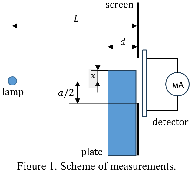
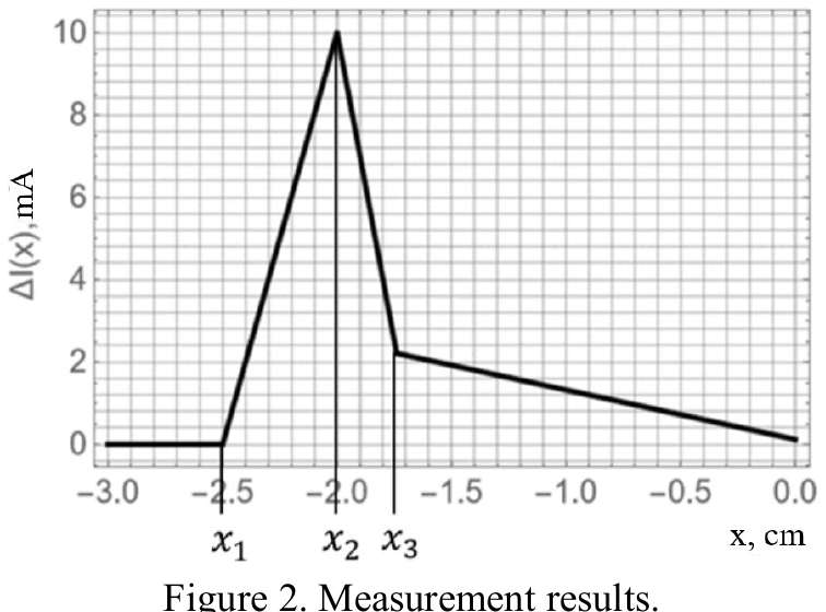
3.6 Express the coordinate values of point in terms of the values .
3.7 Express the coordinate values of point in terms of the values .
3.8 Express the value of at point in terms of the quantities and .
3.9 Express the coordinate values of point in terms of the values .
3.10 Find the slope coefficient of the straight line in the area to the right of point and express it through the quantities .
3.11 Based on the graph and parameters obtained in 3.6-3.10, determine the numerical values of the parameters , as well as the ratio .
3.12 Based on the obtained numerical data, construct the right side of the graph as the coordinate changes from 0.00 cm to 3.00 cm, indicating the coordinates of all characteristic points on the graph.
Mathematical hint for the theoretical competition. The following formulas may be useful:
Topic: Geometric Optics Metodi: Snell’s Law, Ray Tracing Competenze: Diagrammatic Reasoning, Physical Reasoning
Problema 3. Ottica geometrica e fotorivelatore (10,0 punti)
In questo problema vanno studiate le leggi dell’ottica geometrica utilizzando un fotorivelatore, che è un dispositivo in grado di convertire l’energia luminosa in energia elettrica. Si assume che la superficie assorbente del fotorivelatore sia piana e che, quando collegato a un milliammetro, mostri un valore di corrente proporzionale alla potenza della radiazione elettromagnetica assorbita.
L’ottica geometrica è una branca dell’ottica che studia le leggi di propagazione della luce nei mezzi trasparenti, la riflessione della luce sulle superfici specchio e i principi utilizzati per costruire immagini quando la luce attraversa sistemi ottici, senza tenere conto delle sue proprietà ondulatorie. Il concetto fondamentale dell’ottica geometrica è il raggio di luce: ciò implica che la direzione del flusso di energia radiante (la traiettoria del raggio di luce) non dipenda dalle dimensioni trasversali dello stesso. Ricordiamo ora le leggi dell’ottica geometrica necessarie per risolvere questo problema.
3.1 Quando una luce incide su una superficie piana e viene riflessa, il raggio incidente e quello riflesso si trovano nello stesso piano della normale alla superficie di incidenza. Supponiamo che il raggio incidente formi un angolo con la normale, mentre il raggio riflesso forma un angolo . Scrivere la relazione tra questi due angoli.
3.2 Quando la luce proviene dall’aria e incide su una superficie piana di un materiale il cui indice di rifrazione è , sia il raggio incidente che quello rifratto si trovano nello stesso piano della normale nel punto di incidenza. Supponiamo che il raggio incidente formi un angolo con la normale, e che il raggio rifratto formi un angolo . Scrivere la relazione tra questi angoli.
Nelle parti successive di questo problema considereremo soltanto situazioni in cui, nei processi di rifrazione della luce, gli angoli menzionati sopra siano piccoli e si possa applicare l’approssimazione dell’ottica parassiale.
3.3 Riscrivere la risposta al problema 3.2 nel caso in cui gli angoli di incidenza e rifrazione siano piccoli.
In questo problema, si assume che la sorgente di radiazione sia una lampada cilindrica molto lunga e sottile, la cui superficie emette radiazioni in modo uniforme in tutte le direzioni.
3.4 Sia la potenza di radiazione della lampada proveniente da tutta la sua superficie. Determinare la potenza di radiazione concentrata in un angolo piano , come mostrato nella figura.
Lamina sottile
Si supponga che la sorgente di luce descritta sopra illumini uno schermo opaco su cui è stata realizzata una fessura rettangolare larga cm. La lampada è posizionata in modo parallelo ai bordi della fessura, direttamente di fronte al suo centro, a una distanza di cm; immediatamente dietro la fessura è posta la superficie del fotorivelatore in modo da catturare l’intero flusso luminoso che attraversa la fessura. Il fotorivelatore è collegato a un milliammetro. Una sottile lamina rettangolare può muoversi parallelamente allo schermo; il suo bordo superiore è parallelo ai bordi della fessura, e il materiale della lamina è traslucido, con un coefficiente di trasmissione pari a . In assenza della lamina, il milliammetro indica un valore di corrente di mA.
3.5 Sia ora sia la coordinata che va dal centro della fessura al bordo della lamina, con l’asse verticale diretto verso l’alto. Tracciare un grafico che mostri la deviazione delle letture del milliammetro, in «milliammeteres» , rispetto alla lettura iniziale , in funzione della coordinata nell’intervallo da cm a cm. Indicare esplicitamente le coordinate di tutti i punti caratteristici presenti sul grafico.
Lamina spessa
Manteniamo lo stesso schema di osservazione, ma sostituiamo la lamina sottile con una lamina spessa dello spessore , la cui superficie orizzontale è su entrambi i lati uno specchio perfettamente riflettente; inoltre, l’indice di rifrazione del materiale è pari a . Per questa parte, consideriamo i valori numerici dei parametri e come sconosciuti. A scopo di chiarezza, il diagramma dello schema è mostrato nella Figura 1, mentre la Figura 2 riporta i risultati delle misurazioni effettuate nell’intervallo di variazione della coordinata da cm a cm; sono inoltre indicati tre punti caratteristici del grafico: , e . In questo contesto, rappresenta la deviazione delle letture del milliammetro, in «milliammeteres», rispetto alla lettura iniziale effettuata in assenza della lamina.
3.6 Esprimere i valori delle coordinate del punto in termini dei valori .
3.7 Esprimere i valori delle coordinate del punto in termini dei valori .
3.8 Esprimere il valore di nel punto in termini delle grandezze e .
3.9 Esprimere i valori delle coordinate del punto in termini dei valori .
3.10 Trovare il coefficiente di pendenza della retta nell’area a destra del punto ed esprimerlo in termini delle grandezze .
3.11 Sulla base del grafico e dei parametri ottenuti nei punti 3.6-3.10, determinare i valori numerici delle grandezze , nonché il rapporto .
3.12 Sulla base dei dati numerici ottenuti, costruire la parte destra del grafico al variare della coordinata da 0,00 cm a 3,00 cm, indicando le coordinate di tutti i punti caratteristici presenti sul grafico.
Suggerimento matematico per la competizione teorica. Le seguenti formule possono essere utili: