Perdita di velocità nel rimbalzo (55 punti)
La pallina lasciata cadere liberamente sulla tavoletta rimbalza a un’altezza minore di quella di partenza. Con un’altezza di caduta che non supera il mezzo metro, si può ipotizzare che l’effetto della resistenza dell’aria sia trascurabile. Consideriamo trascurabile anche l’effetto dell’inevitabile piccola rotazione indotta con le dita sulla pallina mentre la si abbandona.
Chiameremo coefficiente di restituzione il rapporto fra la velocità del centro di massa della pallina immediatamente dopo l’urto e la velocità immediatamente prima dell’urto:
Questo coefficiente è caratteristico della coppia pallina-tavoletta, a meno che non vi siano deformazioni permanenti sulla pallina.
Attacca sulla tavoletta una striscia di nastro adesivo di carta, in modo da ricoprirla per tutta la sua lunghezza. La zona di tavoletta coperta dal nastro sarà la base per la caduta della pallina. Con nastro adesivo trasparente, attacca su tutta la lunghezza del listello di legno un pezzo del metro di carta. Con lo stesso nastro adesivo fissa al listello la parte più corta dell’angolare metallico. La parte più lunga sarà la base di appoggio del listello. Per una maggiore stabilità, fissa questa base al piano del tavolo con il nastro adesivo di carta, come in figura 1, a sinistra.
Il listello fungerà da catetometro, cioè da misuratore di quote, e deve quindi essere verticale (figura 1, a destra). Una molletta da bucato e l’elastico saranno gli indici sul catetometro rispettivamente per la quota di partenza della pallina e quella (massima) del suo rimbalzo. Realizza il filo a piombo, attaccando i due fermagli alle due estremità del filo da cucito: uno fa da peso, l’altro va appoggiato o appeso alla molletta. Controlla con il filo a piombo che il listello sia verticale.
Per determinare il coefficiente di restituzione, misura l’altezza del rimbalzo facendo cadere la pallina da quote diverse. Non superare i 50 cm come quota di partenza. Devi cercare di afferrare la pallina dopo che è rimbalzata, evitando che cada sul tavolo e poi sul pavimento. A questo scopo disponi un po’ di carta da cucina increspata attorno alla tavoletta.
Mentre è semplice misurare la quota di partenza, è estremamente difficile leggere “al volo” sul catetometro la quota massima nel rimbalzo. È più facile invece confrontare la posizione di un indice sul catetometro, come l’elastico, con la posizione di un punto di riferimento sulla pallina quando questa ha raggiunto la massima altezza.
1.1 — Determina il coefficiente di restituzione, da misure della quota di partenza, di quella del rimbalzo, e da eventuali altre misure. Registra i dati in una tabella.
1.2 — Descrivi il procedimento sperimentale seguito. Indica qual è il punto di riferimento che hai scelto sulla pallina.
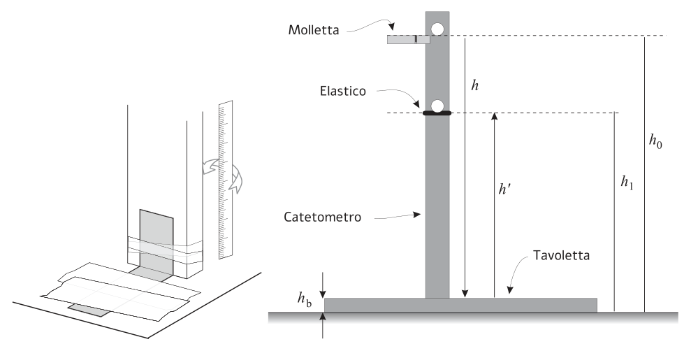 Figura 1: catetometro e simboli quote
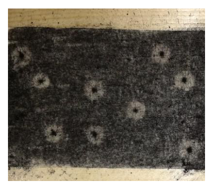 Figura 2: impronta circolare sulla tavoletta
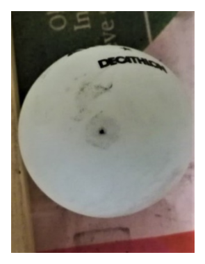 Figura 3: traccia grigia sulla pallina
Topic: Newtonian Mechanics, Conservation of Energy Metodi: Conservation of Energy, Kinematic Equations, Experimental Data Analysis Competenze: Experimental Data Analysis, Physical Reasoning Objects: Ball Fonte: Testo (PDF) — p.3 Soluzione: Soluzioni (PDF)
Loss of speed in the rebound (55 points)
The ball left to fall freely on the board bounces back to a height less than the starting ball. With a drop height of no more than half a meter, the effect of air resistance can be assumed to be negligible. We also consider negligible the effect of the inevitable small spin induced by the fingers on the ball as it is abandoned.
We’ll call the return coefficient ** ** the ratio of the ball’s center of mass immediately after the impact to the speed immediately before the impact:
This coefficient is characteristic of the ball-table torque, unless there are permanent deformities on the ball.
He attaches a strip of paper tape to the tablet so that it covers it for its entire length. The area of the tablet covered by the tape will be the base for the fall of the ball. With transparent adhesive tape, attach a meter of paper to the entire length of the wooden board. The same adhesive tape shall attach the shortest part of the metal angle to the handle. The longer part will be the base of the list. For greater stability, attach this base to the table plane with the paper tape, as shown in Figure 1, left.
The list will act as a cathetometer, i.e. a quota meter, and must therefore be vertical (Figure 1, right). A washing strap and the elastic shall be the indicators on the cathetometer for the ball’s starting and (maximum) bounce ratio respectively. The lead wire is made by attaching the two hinges to the two ends of the sewing thread: one is made of weight, the other is supported or hung from the spring. Use the lead wire to make sure the list is vertical.
To determine the return coefficient, measure the bounce height by dropping the ball from different heights. Not more than 50 cm as starting height. You have to try to grab the ball after it bounces, so it doesn’t fall on the table and then on the floor. For this purpose, you have some kitchen paper cropped around the table.
While it is easy to measure the starting altitude, it is extremely difficult to read “on the fly” on the cathetometer the maximum bounce altitude. It is easier to compare the position of an index on a cathetometer, such as an elastic, with the position of a reference point on the ball when it has reached its maximum height.
1.1 Determine the return coefficient by measuring the starting, bounce and other measures. It records the data in a table.
1.2 Describe the experimental procedure followed. Indicate the reference point you chose on the ball.
Figure 1: Cathetometer and quotation symbols
Figure 2: circular print on the table
Figure 3: grey mark on the ball
Topic: Newtonian Mechanics, Conservation of Energy Metodi: Conservation of Energy, Kinematic Equations, Experimental Data Analysis Competenze: Experimental Data Analysis, Physical Reasoning Objects: Ball Fonte: Testo (PDF) — p.3 Soluzione: Soluzioni (PDF)
Durata dell’urto — Dimensione dell’impronta (50 punti)
Anche se l’urto della pallina appare istantaneo, la sua durata non è nulla, ma solo molto breve. Questa brevissima durata è legata alle intense forze che entrano in gioco durante l’urto, frenando il movimento in un primo tempo e causando poi il rimbalzo della pallina.
Indossa i guanti e annerisci con il carbonico la striscia adesiva di carta sulla tavoletta, per una lunghezza di circa 10 cm. Rendi uniforme lo strato soffiando lo con il batuffolo di cotone.
Se la pallina cade sulla zona annerita, lascia nell’area di contatto una traccia circolare, con un puntino più scuro nel centro (figura 2). Anche sulla superficie della pallina appare una traccia grigia “circolare” (figura 3).
La pallina da ping-pong è fatta di materiale che ha particolari proprietà di durezza e elasticità, grazie alle quali si deforma nell’urto, ma riprende subito dopo la forma iniziale.
Possiamo pensare che la parte inferiore della pallina si appiattisca, rientri in una piccola ammaccatura e torni poi alla forma sferica convessa, e che il processo avvenga senza che si deformi in modo significativo la parte superiore della pallina stessa come indicato nella figura 4 a lato, dove è il raggio della pallina, il raggio della sua traccia, la deformazione in direzione verticale. La figura 4 non è in scala.
Questa deformazione indica di quanto si è spostato verso il basso il punto che fino all’istante dell’impatto era al centro della pallina. La distanza , viene percorsa poi verso l’alto, quando la pallina torna alla forma iniziale.
Dalle dimensioni delle tracce circolari si può risalire alla durata del contatto, facendo la seguente ipotesi: si assume che la forza sulla pallina sia costante nella fase di compressione, e poi ancora costante nel successivo ritorno alla forma sferica, con una discontinuità da una fase all’altra. L’ipotesi, anche se grossolana, consente di stimare la durata dell’urto.
2.1 — Lascia cadere la pallina in modo che il suo centro cada di circa . Annota il valore della quota scelta.
2.2 — Esamina l’impronta lasciata sulla tavoletta e/o quella sulla pallina e, se l’impronta risulta circolare, misurarne il diametro e calcola la deformazione . Registra tutti i dati nella tabella.
2.3 — Determina la durata totale dell’urto, nell’ipotesi suddetta di forze costanti. Non è richiesta l’incertezza di . Limitati a scriverne il valore in notazione scientifica, e con le sole cifre che ritieni significative.
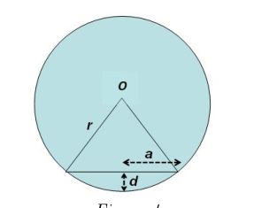 Figura 4: schema deformazione pallina urto
Topic: Newtonian Mechanics, Elasticity & Materials Metodi: Free-Body Diagram, Physical Modeling, Experimental Data Analysis Competenze: Experimental Data Analysis, Estimation & Approximation Objects: Ball Fonte: Testo (PDF) — p.4 Soluzione: Soluzioni (PDF)
**Duration of impact Size of footprint ** (50 points)
Even if the ball’s impact appears instantaneous, its duration is nothing but very short. This very short duration is linked to the intense forces that come into play during the impact, slowing the movement at first and then causing the ball to bounce.
Wear gloves and apply the adhesive tape to the tablet with the carbonic tape, about 10 cm long. You make the layer even by blowing it with the cotton swab.
If the ball falls on the blackened area, it leaves a circular mark in the contact area, with a darker dot in the center (Figure 2). A “circular” grey track appears on the surface of the ball as well (Figure 3).
The ping-pong ball is made of material that has particular hardness and elasticity properties, which make it deform in impact, but recovers immediately after its initial shape.
Possiamo pensare che la parte inferiore della pallina si appiattisca, rientri in una piccola ammaccatura e torni poi alla forma sferica convessa, e che il processo avvenga senza che si deformi in modo significativo la parte superiore della pallina stessa come indicato nella figura 4 a lato, dove è il raggio della pallina, il raggio della sua traccia, la deformazione in direzione verticale. Figure 4 is not in scale.
This deformation indicates how far downward the point has moved which until the moment of impact was at the centre of the ball. The distance , is then traveled upwards, when the ball returns to its original shape.
From the size of the circular tracks, the duration of contact can be traced, assuming that the force on the ball is constant in the compression phase, and then still constant in the subsequent return to the spherical shape, with a discontinuity from one phase to the next. The assumption, although coarse, allows us to estimate the duration of the impact.
**2.1 ** Drop the ball so that its center falls by about . Please note the value of the quota chosen.
2.2 Examine the footprint left on the tablet and/or the ball and, if the footprint is circular, measure the diameter and calculate the deformation . It records all the data in the table.
2.3 Determine the total duration of the impact , in the case of constant forces. The uncertainty of is not required. Just write the value in scientific notation, and only the numbers you think are significant.
Figura 4: schema deformazione pallina urto
Topic: Newtonian Mechanics, Elasticity & Materials Metodi: Free-Body Diagram, Physical Modeling, Experimental Data Analysis Competenze: Experimental Data Analysis, Estimation & Approximation Objects: Ball Fonte: Testo (PDF) — p.4 Soluzione: Soluzioni (PDF)
Durata dell’urto — Carica di un condensatore (75 punti)
Nel circuito della figura 5, una pila è collegata in serie con un condensatore scarico, un resistore, e un interruttore inizialmente aperto (vedi figura 5 a sinistra). Se si chiude per un tempo , con aperto, la differenza di potenziale (d.d.p.) ai capi del condensatore sale al valore , dal valore nullo iniziale, secondo la relazione:
dove è la forza elettromotrice (f.e.m.) fornita dalla pila, (con resistenza del resistore e resistenza interna della pila) e è la capacità del condensatore.
La resistenza interna della pila vale , mentre la resistenza del resistore è indicata sull’etichetta attaccata al resistore stesso.
Se in un circuito come questo si fa in modo che si chiuda (con aperto) quando la pallina è a contatto con la tavoletta, dalla misura della d.d.p. ai capi del condensatore si potrà risalire alla durata del contatto. Se si chiude il condensatore è cortocircuitato e la d.d.p. ai suoi capi si annulla (vedi figura 5 a destra).
Attacca 3 o 4 striscoline o un rettangolino di nastro adesivo di alluminio sulla pallina senza che rimangano grinze, per creare zone conduttrici (figura 6).
Per realizzare , ritaglia 2 pezzi rettangolari (circa) di nastro adesivo di alluminio. Attaccali alla distanza di 1 mm l’uno dall’altro sulla tavoletta, lasciandone sporgere una parte che ripiegherai su se stessa, con l’adesivo all’interno, come mostrato in figura 7. Tale separazione funziona da interruttore che viene chiuso dal contatto con le parti di alluminio applicate sulla pallina quando questa vi cadrà sopra. La faccia gommata del nastro di alluminio non è conduttrice.
Per realizzare , ricopri le estremità dei due bracci della molletta con nastro di alluminio, badando che non si tocchino tra loro, come mostrato in figura 8. Anche tale interruttore verrà chiuso attraverso il contatto con le zone conduttrici della pallina, prima di ogni caduta.
Monta il circuito come indicato in figura 9 corrispondente allo schema elettrico di figura 5.
ATTENZIONE! Il condensatore, che è di tipo elettrolitico, ha un dielettrico sensibile alla direzionalità del campo elettrico interno. Le due polarità sono indicate sull’involucro: il reoforo libero, cioè il filo metallico dalla parte dell’involucro colorata in blu, corrisponde alla polarità negativa e va quindi collegato al polo negativo della pila. SE IL CONDENSATORE È POLARIZZATO INVERSAMENTE, PUÒ ESPLODERE. IN OGNI CASO, USA GLI OCCHIALI DI PROTEZIONE E STANNE LONTANO.
Accendi il multimetro con il tasto “POWER”. Lo strumento è già stato predisposto per funzionare come voltmetro in corrente continua, con portata 20 V. Misura con il voltmetro la f.e.m. ai capi della pila e registrala nel foglio risposte.
Realizza il circuito collegando in serie pila, condensatore + resistore, e . Collega il voltmetro in parallelo al condensatore. Collega anche in parallelo al condensatore. Con la pallina a contatto con , cortocircuita il condensatore per scaricarlo da eventuale carica, e seleziona la portata di 2 V sul voltmetro.
Fissa la molletta (interruttore ) in modo che la pallina cada da un’altezza di 25 cm sopra l’interruttore . Mantieni scarico il condensatore prima di ogni lancio, cortocircuitandolo con la pallina su .
Fai almeno 20 rilevazioni di d.d.p. corrispondenti a lanci andati a buon fine. Otterrai valori di d.d.p. compresi in un certo intervallo. Tieni presente che il condensatore si carica solamente nella fase di chiusura del circuito, la cui durata può non coincidere con quella dell’urto. Tenendo conto di ciò, dovrai scegliere e prendere in considerazione i valori di d.d.p. che più probabilmente sono stati ottenuti in situazione di coincidenza tra chiusura del circuito e urto.
3.1 — Registra l’indicazione del voltmetro ogni volta che il lancio è andato a buon fine e il condensatore si è caricato.
3.2 — Quale/i valore/i scegli per calcolare la durata dell’urto? Quale criterio hai seguito per la scelta?
3.3 — Ricava dalla (1) l’espressione del tempo di carica del condensatore , e calcola la durata dell’urto per il/i valore/i che hai scelto. Non è richiesta l’incertezza di . Limitati a scriverne il valore in notazione scientifica, e con le sole cifre che ritieni significative.
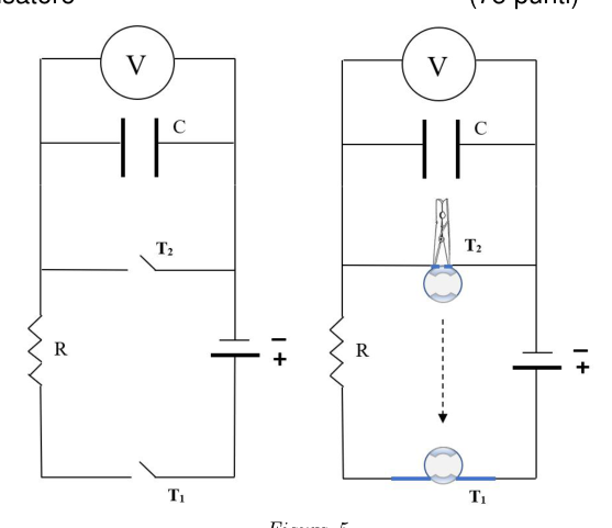 Figura 5: schema circuito carica condensatore
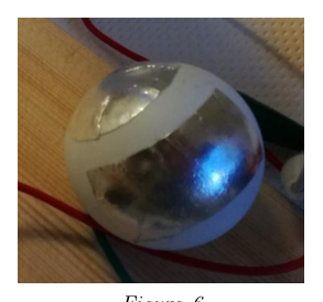 Figura 6: strisce conduttrici sulla pallina
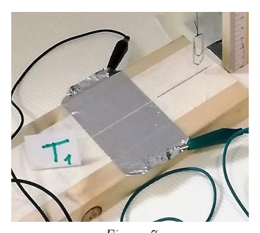 Figura 7: interruttore T1 nastro alluminio
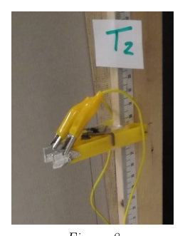 Figura 8: interruttore T2 molletta alluminio
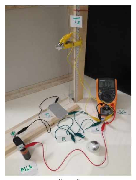 Figura 9: montaggio fisico circuito
Topic: Circuits, Newtonian Mechanics Metodi: Kirchhoff’s Laws, Experimental Data Analysis, Physical Modeling Competenze: Experimental Data Analysis, Physical Reasoning Objects: Ball, Capacitor, Resistor, Battery, Switch Fonte: Testo (PDF) — p.5 Soluzione: Soluzioni (PDF)
Duration of impact Load of a capacitor (75 points)
In the circuit in Figure 5, a battery is connected in series with an exhaust capacitor, resistor, and initially open switch (see Figure 5 on the left). If is closed for a time , with open, the difference in potential (d.d.p.) to capacitor heads rises to , from the initial zero value, according to the ratio:
where is the electromotive force (f.e.m.) provided by the battery, (with resistance and internal battery resistance) and is the capacitance of the capacitor.
The internal resistance of the battery is , while the resistance of the battery is indicated on the label attached to the resistor itself.
If in a circuit like this is closed (with open) when the ball is in contact with the board, the measurement of the d.d.p. The capacitor heads can be traced back to the duration of contact. If is closed, the capacitor is short and the d.d.p. The Commission has also adopted a number of measures to ensure that the Commission’s proposals are implemented in a manner consistent with the objectives of the programme.
Attach 3 or 4 strips or a rectangle of aluminium adhesive tape to the ball without any grinding to create conductive zones (Figure 6).
To make , cut 2 rectangular pieces (approximately) of aluminium adhesive tape. Attach them to each other at a distance of 1 mm on the tablet, leaving a part to fold onto itself, with the adhesive inside, as shown in Figure 7. This separation functions as a switch that is closed by contact with the aluminium parts applied to the ball when it falls over it. The rubber face of the aluminum tape is not conductive.
To make , cover the ends of the two arms of the spring with aluminium tape, making sure they do not touch each other, as shown in Figure 8. This switch shall also be closed by contact with the ball conducting areas before each fall.
Install the circuit as shown in Figure 9 corresponding to the electrical scheme in Figure 5.
The capacitor, which is of an electrolytic type, has a dielectric sensitive to the direction of the internal electric field. The two polarities are indicated on the envelope: the free reopening, i.e. the metallic wire on the blue-colored part of the envelope, corresponds to the negative polarity and must therefore be connected to the negative pole of the pile. If the condenser is extremely polarized, it can explode. In all cases, use protection tools and stand away.
Turn on the multimeter with the “POWER” button. The instrument has already been prepared to operate as a DC voltmeter with a power output of 20 V. Measure the f.e.m. with the voltmeter. to the pile heads and record it in the reply sheet.
It connects the circuit in series with the battery, capacitor + resistor, and . It connects the voltmeter in parallel to the capacitor. It also connects in parallel to the capacitor. With the ball in contact with , short circuit the capacitor to discharge it from any charge, and select the 2 V voltage on the voltmeter.
Fix the spring (switch ) so that the ball falls from a height of 25 cm above the switch . Keep the capacitor discharged before each launch, by short-circulating it with the ball on .
You do at least 20 D.D.P. tests. The results of the tests were the same as those of the previous tests. You’ll get D.D.P. values. The Commission has already adopted a number of proposals. Please note that the capacitor is charged ** only during the circuit shutdown phase **, the duration of which may not coincide with that of the impact. In view of this, you will have to choose and consider the values of d.d.p. The following conditions are most likely to be met in the event of a collision between the circuit and the shutdown.
3.1 Record the voltmeter indication every time the launch has been successful and the capacitor has been charged.
3.2 What value/values do you choose to calculate the duration of the impact? What criteria did you follow for the choice?
3.3 Draw from (1) the expression of the capacitor load time , and calculate the duration of impact for the value (s) you have chosen. The uncertainty of is not required. Just write the value in scientific notation, and only the numbers you think are significant.
The following information shall be provided:
Figure 6: conductive stripes on the ball
The following table shows the number of units in the unit:
The following is the list of the components of the engine:
The following table shows the results of the calculation of the total value of the input data:
Topic: Circuits, Newtonian Mechanics Metodi: Kirchhoff’s Laws, Experimental Data Analysis, Physical Modeling Competenze: Experimental Data Analysis, Physical Reasoning Objects: Ball, Capacitor, Resistor, Battery, Switch Fonte: Testo (PDF) — p.5 Soluzione: Soluzioni (PDF)
Fonti di errori sistematici per la durata dell’urto (20 punti)
Visti i valori della durata dell’urto ottenuti nelle due sezioni precedenti, considera ciascuno dei due procedimenti seguiti.
4.1 — Illustra brevemente quali sono le fonti di errori sistematici che, secondo te, possono aver influito sui risultati in ciascuno dei due procedimenti, e se questi errori sono per eccesso o per difetto.
Topic: Newtonian Mechanics, Elasticity & Materials Metodi: Experimental Data Analysis, Error Propagation, Physical Modeling Competenze: Experimental Data Analysis, Physical Reasoning Objects: Ball Fonte: Testo (PDF) — p.7 Soluzione: Soluzioni (PDF)
The following information shall be provided:
In view of the impact duration values obtained in the two previous sections, consider each of the two procedures followed.
4.1 Briefly explain what are the sources of systemic errors that you think may have influenced the results in each of the two procedures, and whether these errors are excessive or defective.
Topic: Newtonian Mechanics, Elasticity & Materials Metodi: Experimental Data Analysis, Error Propagation, Physical Modeling Competenze: Experimental Data Analysis, Physical Reasoning Objects: Ball Fonte: Testo (PDF) — p.7 Soluzione: Soluzioni (PDF)