In questo problema discutiamo un modello semplificato di accelerometro progettato per attivare l’air bag di automobili in caso di scontro. Si vuole costruire un sistema elettromeccanico in modo che quando l’accelerazione supera un certo limite uno dei parametri elettrici del sistema, come la tensione fra due punti del circuito, supera un certo valore di soglia e di conseguenza viene attivato l’air bag.
Nota: In questo problema non considerare la gravità.
Considera un condensatore piano con armature parallele, come in Figura 1. L’area di ciascuna armatura è e la distanza fra di esse è , molto minore delle dimensioni delle due armature. Un’armatura è attaccata ad una parete per mezzo di una molla con costante elastica , mentre l’altra armatura è fissa. Quando la distanza fra le armature è la molla non è né compressa né stirata; in altre parole in questa situazione sulla molla non si esercita alcuna forza. Per la costante dielettrica dell’aria fra le armature puoi prendere quella del vuoto, . A questa distanza fra le armature la capacità del condensatore è . In queste condizioni mettiamo sulle armature delle cariche elettriche e , e lasciamo che il sistema raggiunga l’equilibrio meccanico.
1.1 Calcola la forza elettrica, , che si esercita fra le armature. [0.8]
1.2 Sia lo spostamento dell’armatura legata alla molla. Trova . [0.6]
1.3 In questa situazione, qual è la differenza di potenziale elettrico fra le armature, espressa in termini di , , , ? [0.4]
1.4 Sia la capacità del condensatore, definita come il rapporto fra carica e differenza di potenziale. Trova in funzione di , , , . [0.3]
1.5 Qual è l’energia totale, , immagazzinata nel sistema, espressa in termini di , , , ? [0.6]
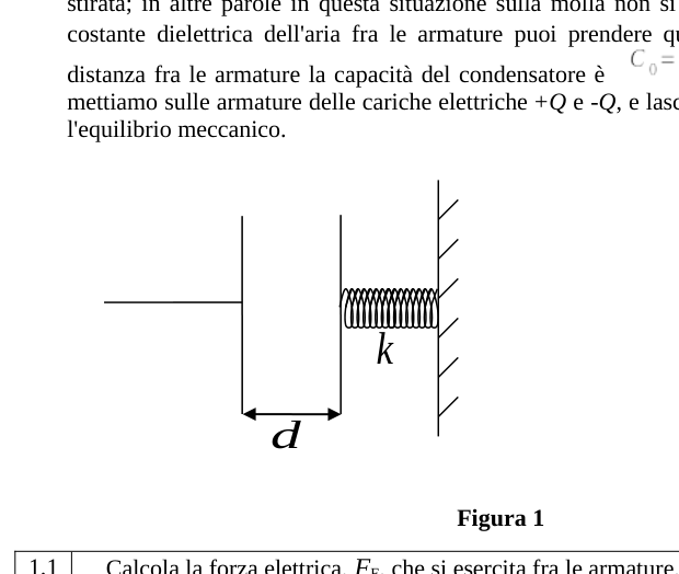 Condensatore piano con molla e cariche
Topic: Electrostatics, Oscillations & Waves Metodi: Electric Potential Method, Hooke’s Law, Energy Conservation Method Competenze: Mathematical Modeling, Physical Reasoning Objects: Capacitor, Spring Fonte: Testo (PDF) — p.1 Soluzione: Soluzioni (PDF)
In this problem, we discuss a simplified model of accelerometer designed to activate the car airbag in the event of a collision. The aim is to build an electromechanical system so that when the acceleration exceeds a certain limit one of the system’s electrical parameters, such as the voltage between two points in the circuit, exceeds a certain threshold value and the air bag is activated.
Note: In this problem do not consider gravity.
Consider a flat capacitor with parallel armor, as in Figure 1. The area of each armor is and the distance between them is , much smaller than the size of the two armor. One armor is attached to one wall by means of a constantly elastic spring , while the other armor is fixed. When the distance between the frames is the spring is neither compressed nor stretched; in other words, in this situation no force is applied to the spring. For the dielectric constant of the air between the armor, you can take the vacuum constant, . At this distance between the frames the capacitor capacity is . In these conditions, we put the electrical charges and on the armor, and let the system reach mechanical equilibrium.
1.1 Calculates the electrical force, , exerted between the frames. [0.8]
1.2 Whether the movement of the spring-bound armor. Find the . [0.6]
1.3 In this situation, what is the difference in electrical potential between the frames, expressed in terms of , , , ? [0.4]
1.4 Whether the capacitor capacity, defined as the ratio of charge to potential difference. Find as a function of , , , . [0.3]
1.5 What is the total energy, , stored in the system, expressed in terms of , , , ? [0.6]
*Flat capacitor with spring and load *
Topic: Electrostatics, Oscillations & Waves Metodi: Electric Potential Method, Hooke’s Law, Energy Conservation Method Competenze: Mathematical Modeling, Physical Reasoning Objects: Capacitor, Spring Fonte: Testo (PDF) — p.1 Soluzione: Soluzioni (PDF)
Considera ora la Figura 2, dove si vede una massa attaccata ad una piastra conduttrice di massa trascurabile ed anche a due molle che hanno la stessa costante elastica . La piastra conduttrice si può muovere avanti e indietro nello spazio compreso fra due piastre conduttrici fisse. Tutte queste piastre sono simili fra loro e hanno la stessa area . In questo modo le tre piastre costituiscono due condensatori. Come si vede in Figura 2, le piastre fisse sono collegate a generatori di potenziale costante e , e la piastra di mezzo è collegata a terra mediante un interruttore a due vie. Il filo connesso alla piastra mobile non ne disturba il moto e le tre piastre rimangono sempre parallele. Quando tutto il sistema non è accelerato, la distanza fra la piastra mobile e ciascuna di quelle fisse è , che è molto minore delle dimensioni delle piastre. Puoi trascurare lo spessore della piastra mobile.
L’interruttore si può trovare in due posizioni, e . Considera che il sistema di condensatori, montato su un’automobile, venga accelerato con accelerazione costante. Fai l’ipotesi che durante questa accelerazione costante le molle non oscillino e tutti i componenti di questo sistema di condensatori siano nelle loro posizioni di equilibrio, cioè non si muovano uno rispetto all’altro né rispetto all’automobile. A causa dell’accelerazione, la piastra mobile risulta spostata di una certa quantità rispetto al punto di mezzo fra le due piastre fisse.
Considera il caso in cui l’interruttore si trova nella posizione , cioè la piastra mobile è connessa direttamente a terra con un filo; allora
2.1 Trova la carica su ciascun condensatore in funzione di . [0.4]
2.2 Trova la forza elettrica risultante, , che agisce sulla piastra mobile, in funzione di . [0.4]
2.3 Adesso fai l’approssimazione e trascura quindi i termini dell’ordine di rispetto a quelli dell’ordine di . Ottieni di conseguenza un’espressione semplificata di quanto ottenuto al punto 2.2. [0.2]
2.4 Scrivi ora la forza totale agente sulla piastra mobile (la somma delle forze elettrica e delle molle) nella forma e trova l’espressione di . [0.7]
2.5 Ed esprimi l’accelerazione costante in funzione di . [0.4]
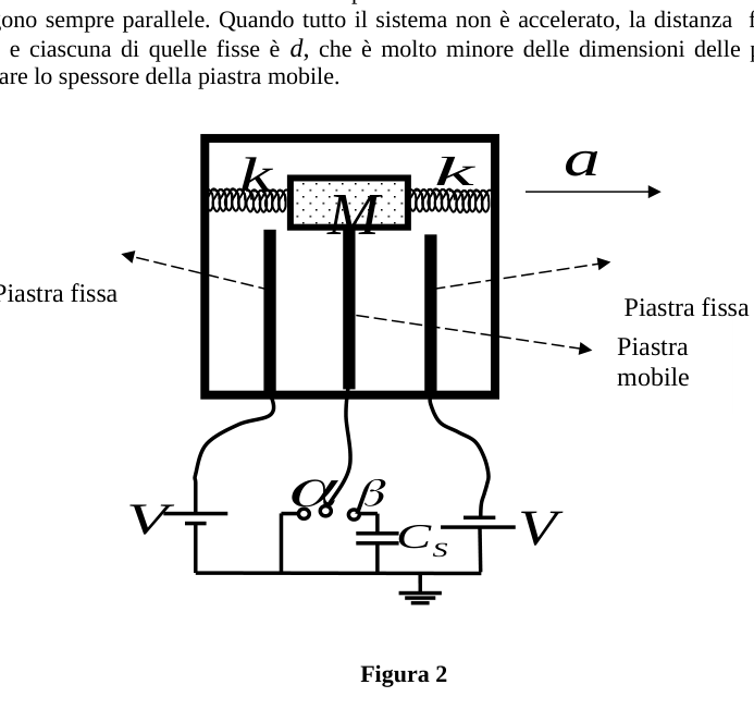 Accelerometro con piastra mobile e interruttore
Topic: Electrostatics, Circuits, Newtonian Mechanics Metodi: Electric Potential Method, Hooke’s Law, Approximation & Series Expansion Competenze: Mathematical Modeling, Physical Reasoning Objects: Capacitor, Spring Fonte: Testo (PDF) — p.2 Soluzione: Soluzioni (PDF)
Consider now Figure 2, where you see a mass attached to a conductive plate of negligible mass and also to two springs that have the same elastic constant . The conductive plate can be moved back and forth in the space between two fixed conductive plates. All these plates are similar to each other and have the same area . Thus the three plates form two capacitors. As shown in Figure 2, the fixed plates are connected to constant power generators and , and the middle plate is connected to the ground by a two-way switch. The wire connected to the movable plate does not disturb the motion of the plate and the three plates remain always parallel. When the whole system is not accelerated, the distance between the moving plate and each of the fixed plates is , which is much smaller than the plates. You can overlook the thickness of the moving plate.
The switch can be found in two positions, and . Consider that the condenser system, mounted on an automobile, is accelerated with a constant acceleration. Assume that during this constant acceleration the springs do not oscillate and all the components of this condenser system are in their equilibrium positions, that is, they do not move relative to each other or relative to the car. Due to acceleration, the movable plate is moved by a certain amount from the midpoint between the two fixed plates.
Consider the case where the switch is in the position , i.e. the mobile plate is connected directly to the ground by a wire; then
Find the charge on each capacitor as a function of . [0.4]
Find the resulting electrical force, , acting on the movable plate, as a function of . [0.4]
Now you make the approximation and then you ignore the terms of the order of over those of the order of . You therefore get a simplified expression of what you get in point 2.2. [0.2]
2.4 Now write the total agent force on the movable plate (the sum of the electrical forces and springs) in the form and find the expression . [0.7]
2.5 And express the constant acceleration as a function of . [0.4]
Moving plate accelerometer and switch
Topic: Electrostatics, Circuits, Newtonian Mechanics Metodi: Electric Potential Method, Hooke’s Law, Approximation & Series Expansion Competenze: Mathematical Modeling, Physical Reasoning Objects: Capacitor, Spring Fonte: Testo (PDF) — p.2 Soluzione: Soluzioni (PDF)
Considera ora il caso in cui l’interruttore sia nella posizione , cioè la piastra mobile sia collegata a terra attraverso un condensatore di capacità (su cui non c’è carica iniziale). Se la piastra mobile si sposta dalla posizione centrale di una lunghezza ,
3.1 Trova, in funzione di , la differenza di potenziale ai capi del condensatore di capacità . [1.5]
3.2 Facendo ora anche in questo caso l’approssimazione e trascurando i termini dell’ordine di rispetto a quelli dell’ordine di , semplifica l’espressione ottenuta al punto 3.1. [0.2]
Topic: Electrostatics, Circuits Metodi: Electric Potential Method, Approximation & Series Expansion, Equivalent Circuit Reduction Competenze: Mathematical Modeling, Physical Reasoning Objects: Capacitor Fonte: Testo (PDF) — p.3 Soluzione: Soluzioni (PDF)
Consider now the case where the switch is in the position, i.e. the mobile plate is connected to the ground through a capacitor (which has no initial charge). If the movable plate moves from its central position of a length ,
Find, by , the difference in potential to capacitor heads . [1.5]
3.2 Now, by making the approximation again in this case and ignoring the terms of the order over those of the order , simplify the expression obtained in point 3.1. [0.2]
Topic: Electrostatics, Circuits Metodi: Electric Potential Method, Approximation & Series Expansion, Equivalent Circuit Reduction Competenze: Mathematical Modeling, Physical Reasoning Objects: Capacitor Fonte: Testo (PDF) — p.3 Soluzione: Soluzioni (PDF)
Si vogliono regolare i parametri in questo problema in modo tale che l’air bag non venga attivato nelle frenate normali, ma in uno scontro si apra abbastanza presto per impedire alla testa del guidatore di andare a sbattere contro il parabrezza o il volante. Come hai visto nella sezione 2, la forza esercitata dalle molle e dalle cariche elettriche sulla piastra mobile può essere descritta come quella di una molla di costante elastica effettiva . L’intero sistema di condensatori, sotto l’effetto di un’accelerazione (che in questo problema è l’accelerazione dell’automobile), si comporta come un sistema massa e molla di massa e costante elastica .
Nota: In questa parte del problema, l’approssimazione che la massa e la molla siano in equilibrio in presenza di un’accelerazione costante e quindi non si muovano rispetto all’automobile, non è più valida.
Trascura l’attrito ed usa i seguenti valori numerici per i parametri del problema: , , , , , .
4.1 Con questi dati trova il rapporto fra la forza elettrica calcolata al punto 2.3 e la forza esercitata dalle molle e mostra che le forze elettriche possono essere trascurate rispetto a quelle meccaniche. [0.6]
Anche se non abbiamo calcolato le forze elettriche nel caso in cui l’interruttore sia nella posizione , si può dimostrare analogamente che anche in questo caso le forze elettriche sono piccole e trascurabili.
4.2 Se l’automobile, mentre viaggia a velocità costante, improvvisamente frena con accelerazione costante , quanto è lo spostamento massimo della piastra mobile? Dai la risposta in termini dei parametri. [0.6]
Consideriamo il caso in cui l’interruttore è nella posizione ; il sistema è stato progettato in modo che l’air bag venga attivato quando la tensione ai capi del condensatore verso massa raggiunga il valore . Si vuole che l’air bag non venga attivato in caso di normale frenata, e quindi quando l’accelerazione dell’automobile è meno dell’accelerazione di gravità , ma venga attivato per valori maggiori.
4.3 A questo scopo quanto dev’essere ? [0.6]
Si vuole ancora vedere se l’air bag viene attivato abbastanza rapidamente per impedire che la testa del guidatore urti contro il parabrezza o il volante. Fai l’ipotesi che, per effetto di un urto, l’automobile subisca una decelerazione pari a ma la testa del guidatore continui a velocità costante.
4.4 Facendo ragionevoli stime della distanza fra la testa del guidatore e il volante, trova il tempo che impiega la testa a battere nel volante. [0.8]
4.5 Trova il tempo che ci vuole perché si raggiunga il segnale di attivazione dell’air bag e confrontalo con . L’air bag è attivato in tempo? Si può supporre che il tempo di apertura dell’air bag, dopo l’attivazione, sia istantaneo. [0.9]
Topic: Newtonian Mechanics, Circuits, Electrostatics Metodi: Simple Harmonic Motion Analysis, Kinematic Equations, Dimensional Analysis Competenze: Estimation & Approximation, Mathematical Modeling Objects: Capacitor, Spring Fonte: Testo (PDF) — p.3 Soluzione: Soluzioni (PDF)
The parameters in this problem are to be adjusted so that the airbag is not activated in normal brakes, but in a collision it opens early enough to prevent the driver’s head from hitting the windscreen or steering wheel. As you saw in Section 2, the force exerted by springs and electrical charges on the moving plate can be described as that of a springs with an effective elastic constant . The entire condenser system, under the effect of an acceleration (which in this problem is the acceleration of the car), behaves as a mass and mass spring and elastic constant system.
Note: In this part of the problem, the approximation that the mass and spring are in equilibrium in the presence of constant acceleration and therefore do not move relative to the car is no longer valid.
Trace the friction and use the following numerical values for the problem parameters: , , , , , .
4.1 Con questi dati trova il rapporto fra la forza elettrica calcolata al punto 2.3 e la forza esercitata dalle molle e mostra che le forze elettriche possono essere trascurate rispetto a quelle meccaniche. [0.6]
Although we have not calculated the electrical forces in the case where the switch is in the position, it can be shown similarly that in this case the electrical forces are small and negligible.
4.2 If the car, while travelling at constant speed, suddenly brakes at constant acceleration , what is the maximum shift of the movable plate ? Give me the answer in terms of parameters. [0.6]
Consider the case where the switch is in the position; the system is designed so that the air bag is activated when the voltage at the capacitor heads to mass reaches . The airbag is not to be activated in the event of normal braking, and therefore when the acceleration of the car is less than the acceleration of gravity , but is activated for higher values.
4.3 A questo scopo quanto dev’essere ? [0.6]
It remains to be seen whether the airbag is activated quickly enough to prevent the driver’s head from hitting the windscreen or the steering wheel. Assume that the car is decelerated by as a result of a collision, but the driver’s head continues at a constant speed.
4.4 By making reasonable estimates of the distance between the driver’s head and the steering wheel, find the time the head takes to beat the steering wheel. [0.8]
4.5 Trova il tempo che ci vuole perché si raggiunga il segnale di attivazione dell’air bag e confrontalo con . Is the air bag activated in time? The airbag opening time after activation may be assumed to be instantaneous. [0.9]
Topic: Newtonian Mechanics, Circuits, Electrostatics Metodi: Simple Harmonic Motion Analysis, Kinematic Equations, Dimensional Analysis Competenze: Estimation & Approximation, Mathematical Modeling Objects: Capacitor, Spring Fonte: Testo (PDF) — p.3 Soluzione: Soluzioni (PDF)