Prueba experimental. Determinación de la capacidad de un condensador
Objetivo. Se va a estudiar experimentalmente el proceso de carga de un condensador a través de una resistencia, y se deducirá la capacidad del condensador.
Materiales.
- Condensador electrolítico
- Pila de petaca.
- Resistencia eléctrica.
- Polímetro con dos sondas y dos pinzas de conexión (cocodrilos).
- Dos cables con pinzas.
- Cronómetro.
Modelo teórico. Un condensador es un dispositivo que sirve para almacenar carga eléctrica. La principal característica de un condensador es su capacidad, , cociente entre la carga que almacena y la diferencia de potencial entre sus terminales.
En este experimento se va a cargar un condensador inicialmente descargado a través de una resistencia, , alimentando el circuito con una pila eléctrica, como se esquematiza en la figura 1. Tras cerrar el circuito, la corriente que circula empieza a cargar el condensador, de forma que aumenta la diferencia de potencial entre sus terminales. Por tanto, la caída de potencial en la resistencia y la corriente que circula por ella van disminuyendo. En concreto, puede demostrarse que la corriente disminuye exponencialmente con el tiempo, , en la forma
donde es la corriente inicial, cuando se cierra el circuito en .
Procedimiento experimental
-
Mida con el polímetro el valor de la resistencia .
-
Con los componentes eléctricos de que dispone construya el circuito eléctrico, dejando inicialmente abierta una de las conexiones a la pila. Tenga en cuenta que:
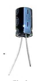
- El condensador electrolítico tiene una polaridad eléctrica definida (ver figuras). Si no se respeta esta polaridad, el condensador se estropeará al cerrar el circuito y las medidas no serán correctas.
- El polímetro se usa como miliamperímetro, en la escala de 2 mA. Antes de cerrar el circuito, asegúrese de que las conexiones de este instrumento son correctas.
- El condensador debe estar inicialmente descargado. Para conseguirlo, basta cortocircuitar sus dos terminales con uno de los cables. (Fig. 2)
- Cierre el circuito y, simultáneamente, ponga en marcha el cronómetro. Anote el valor de la corriente que circula a intervalos regulares de 10 segundos, hasta un valor máximo de 120 s. La lectura del polímetro no es instantánea, por lo que no debe tener en cuenta para cálculos posteriores la medida en el instante inicial, . Presente las medidas de en la segunda columna de una tabla como la siguiente.
| (s) | ( ) |
|---|---|
| 10 | |
| 20 | |
| 120 |
-
Transforme la ecuación (1) para obtener una dependencia lineal entre alguna función de y el tiempo . Anote en la tercera columna de la tabla anterior los valores de esta función de .
-
Represente gráficamente en el papel milimetrado los puntos correspondientes a esta dependencia lineal.
-
Determine la pendiente, , y la ordenada en el origen, , de la recta que mejor se ajusta a estos puntos.
-
A partir de los valores de y obtenidos en 6) y del valor de medido en 1), determine los valores de la corriente inicial, , y de la capacidad del condensador, .
-
Suponga que la principal fuente de error en este experimento es la medida de la corriente , y que la incertidumbre de cada medida es una unidad en el último dígito presentado en la pantalla del polímetro. Haga una estimación de las incertidumbres de y de .
 RC circuit with battery and ammeter
Topic: Circuits, Electrostatics Metodi: Experimental Data Analysis, Graph Linearization, Error Propagation Competenze: Experimental Data Analysis, Graph Linearization Objects: Capacitor, Resistor, Battery, Switch Fonte: Testo (PDF) — p.1
La prova sperimentale. Determinazione della capacità di un condensatore**
Obiettivo. Si studierà sperimentalmente il processo di carico di un condensatore attraverso una resistenza, e si deducerà la capacità del condensatore.
Materiali.
- Condensatore elettrolitico
- Un sacco di petchetti.
- Resistenza elettrica.
- Polímetro con due sonde e due pinze di connessione (coccodrilli).
- Due fili con pinze.
- Un cronometro.
Modello teorico. Un condensatore è un dispositivo che serve per memorizzare una carica elettrica. La caratteristica principale di un condensatore è la sua capacità, , coefficiente tra la carica che immagazzina e la differenza di potenziale tra i suoi terminali.
In questo esperimento si sta per caricare un condensatore inizialmente scaricato attraverso una resistenza, , alimentando il circuito con una pila elettrica, come schematizzato nella figura 1. Dopo aver chiuso il circuito, il corrente circolante inizia a caricare il condensatore, aumentando così il differenziale di potenziale tra i suoi terminali. Pertanto, la caduta di potenziale nella resistenza e il corrente che circola attraverso di essa diminuiscono. In particolare, si può dimostrare che il corrente diminuisce esponenzialmente nel tempo, , in forma
in cui è il corrente iniziale, quando il circuito è chiuso in .
Processo sperimentale
-
Misura con il polimetro il valore della resistenza .
-
Con i componenti elettrici a disposizione costruire il circuito elettrico, lasciando aperta inizialmente una delle connessioni alla pila. Si noti che:
- Il condensatore elettrolitico ha una polarità elettrica definita (vedi figure). Se questa polarità non viene rispettata, il condensatore si danneggerà quando si chiude il circuito e le misure non saranno corrette.
- Il polimetro è usato come millimetro, su scala di 2 mA. Prima di chiudere il circuito, assicurati che le connessioni di questo strumento siano corrette.
- Il condensatore deve essere inizialmente scaricato. Per farlo, basta abbattere i due terminali con uno dei cavi. (Fig. 2)
- Chiudere il circuito e, contemporaneamente, avviare il cronometro. Nota il valore del corrente che circola a intervalli regolari di 10 secondi, fino a un valore massimo di 120 s. La lettura del polimetro non è istantanea, quindi non deve essere tenuta conto per ulteriori calcoli della misurazione all’istante iniziale, . Indicare le misure di nella seconda colonna di una tabella come segue.
| (s) | ( ) |
|---|---|
| 10 | |
| 20 | |
| 120 |
-
Trasforma l’equazione (1) per ottenere una dipendenza lineare tra una funzione di e il tempo . Nota nei valori di questa funzione di nella terza colonna della tabella precedente.
-
Rappresenta graficamente sul cartazzino in millimetri i punti corrispondenti a questa dipendenza lineare.
-
Determina la pendice, , e la pendice ordinata all’origine, , della retta che meglio si adatta a questi punti.
-
Sulla base dei valori di e ottenuti in 6) e del valore di misurato in 1), determinare i valori di corrente iniziale, , e di capacità del condensatore, .
-
Supponiamo che la principale fonte di errore in questo esperimento sia la misura del corrente , e che l’incertezza di ogni misura sia un unità nell’ultimo digitato presentato sullo schermo del polimetro. Estima le incertezze di e di .
RC circuit with battery and ammeter
Topic: Circuits, Electrostatics Metodi: Experimental Data Analysis, Graph Linearization, Error Propagation Competenze: Experimental Data Analysis, Graph Linearization Objects: Capacitor, Resistor, Battery, Switch Fonte: Testo (PDF) — p.1
The test is carried out in a laboratory. Determination of the capacity of a capacitor**
The Commission shall adopt delegated acts in accordance with Article 21 of this Regulation. The process of loading a capacitor through a resistor is to be experimentally studied, and the capacitance of the capacitor is to be deduced.
The following table shows the manufacturer’s specifications for the product:
- Electrolytic capacitor
- A pile of stakes.
- Electrical resistance.
- Polymer with two probes and two connecting pins (crocodiles).
- Two wire with tweezers.
- It’s a timekeeper.
Theoretical model of the system A capacitor is a device used to store electrical charge. The main characteristic of a capacitor is its capacity, , the ratio between the load it stores and the potential difference between its terminals.
In this experiment, a capacitor initially discharged through a resistor, , is charged, feeding the circuit with an electric battery, as outlined in Figure 1. After the circuit is closed, the current circulating begins to charge the capacitor, increasing the potential difference between its terminals. Therefore, the potential drop in resistance and the current flowing through it are decreasing. In particular, it can be shown that the current decreases exponentially over time, , in the form of
where is the starting current, when the circuit is closed at .
The following information is provided by the Commission:
-
Measure with the polymer the resistance value .
-
With the electrical components at your disposal, build the electrical circuit, initially leaving one of the stack connections open. Please note that:
- The electrolytic capacitor has a defined electrical polarity (see Figures). If this polarity is not respected, the capacitor will break when the circuit is closed and the measurements will not be correct.
- The polymer is used as a millimeter, on the 2 mA scale. Before closing the circuit, make sure that the connections to this instrument are correct.
- The capacitor must be initially discharged. To do this, you just need to short-circuit your two terminals with one of the wires. (Fig. 69) 2)
- Close the circuit and start the chronometer at the same time. Note the value of the current circulating at regular intervals of 10 seconds, up to a maximum value of 120 s. The reading of the polymer is not instantaneous, so the measurement at the initial instant, , should not be taken into account for subsequent calculations. Present the measurements of in the second column of a table as follows.
| (s) | ( ) |
|---|---|
| 10 | |
| 20 | |
| 120 |
-
Transform equation (1) to obtain a linear dependence between some function of and time . Note in the third column of the table above the values of this function.
-
Graphically represent the points corresponding to this linear dependence on the millimeter paper.
-
Determine the slope, , and the ordered at the origin, , of the straight line that best fits these points.
-
From the values of and obtained in 6) and the value of measured in 1), determine the values of the initial current, , and the capacitor capacity, .
-
Suppose the main source of error in this experiment is the current measurement , and that the uncertainty of each measurement is a unit in the last digit presented on the polymer screen. Estimate the uncertainties of and .
RC circuit with battery and ammeter
Topic: Circuits, Electrostatics Metodi: Experimental Data Analysis, Graph Linearization, Error Propagation Competenze: Experimental Data Analysis, Graph Linearization Objects: Capacitor, Resistor, Battery, Switch Fonte: Testo (PDF) — p.1