P3. El giróscopo interferencial de fibra óptica
Un giróscopo mecánico es un aparato consistente en un disco que gira rápidamente sobre un eje libre que, debido a la conservación del momento angular, tiende a mantenerse en una dirección constante. Fue inventado por el físico francés Jean Bernard Léon Foucault (1819–1868) y se utiliza habitualmente para mantener la orientación en el espacio, en particular para la estabilización del rumbo de barcos, aviones y satélites. Pero existen otros dispositivos no mecánicos, más precisos, versátiles y sencillos, que se usan con los mismos fines.
El también físico francés Georges Sagnac descubrió en 1911 que “una onda electromagnética que se mueve en un camino cerrado es influenciada por la velocidad angular del sistema”. Basados en el llamado “efecto Sagnac”, a partir de 1960 comenzó la utilización de los giróscopos ópticos, que derivaron en 1970 en los giróscopos interferenciales de fibra óptica. En este ejercicio se describen, de forma simplificada, estos giróscopos.
Como ejercicio preliminar, considere que un haz de luz láser, de longitud de onda (en el vacío), se propaga con velocidad por una fibra óptica rectilínea, de índice de refracción efectivo , que se mueve longitudinalmente con velocidad .
Nota: El índice de refracción efectivo hace referencia a la velocidad de avance de la luz a lo largo del eje de la fibra, , donde es la velocidad de la luz en el vacío.
a1) Determine el tiempo que tarda la luz en recorrer una longitud de fibra, cuando dicha luz se propaga en el mismo sentido que se mueve la fibra (Fig. 1a), y el tiempo cuando lo hace en sentido opuesto (Fig. 1b).
a2) Determine la diferencia entre estos dos tiempos, . Aproxime el resultado teniendo en cuenta que .
Considere ahora que la fibra óptica se curva en una circunferencia de longitud , y que gira con velocidad angular en torno a su centro en sentido horario. Por la fibra se propagan dos haces de luz en sentidos opuestos.
b) Determine la diferencia entre los tiempos y que tarda la luz en recorrer el anillo circular de longitud en sentidos horario y antihorario, respectivamente (Fig. 2a y 2b). Exprese el resultado en función del área del anillo.
El funcionamiento de un giróscopo de fibra óptica se esquematiza en la Fig. 3. Un 50% de la luz emitida por el láser se refleja en el divisor de haz (+), recorre espiras circulares de fibra en sentido horario y, tras reflejarse en el divisor de haz, incide en el detector. El otro 50% de la luz se transmite a través del divisor de haz (−), recorre las espiras en sentido antihorario e incide en el detector después de transmitirse a través del divisor.
Si el dispositivo no gira (), al detector llegan dos haces coherentes que han recorrido el mismo camino óptico y que, por tanto, se superponen en fase e interfieren constructivamente. Sin embargo, cuando todo el conjunto de la Fig. 3 gira con velocidad angular en torno al centro de las espiras, entre ambos haces habrá una diferencia de fase que cambiará el estado interferencial en el detector (efecto Sagnac). Determine:
c1) La diferencia entre los tiempos que tardan los dos haces en llegar al detector, , cuando el dispositivo gira con una velocidad en torno a su centro.
c2) La diferencia de fase, , entre los dos haces de luz.
En los giróscopos de fibra óptica, el sistema optoelectrónico de detección analiza el estado interferencial de los dos haces, determina esta diferencia de fase y permite deducir con gran precisión la velocidad angular de rotación y, en consecuencia, los cambios de rumbo.
d) Determine la mínima velocidad angular de rotación, , para que ambos haces interfieran destructivamente en el detector, de forma que se anule la intensidad total.
Suponga que el sistema de detección es capaz de apreciar variaciones de la diferencia de fase .
e) Con los datos que se indican a continuación, calcule la precisión con que es posible obtener la velocidad angular de rotación.
- Radio de las espiras de fibra óptica:
- Número de espiras:
- Índice de refracción efectivo de la fibra:
- Longitud de onda (en el vacío) del láser:
- Velocidad de la luz en el vacío:
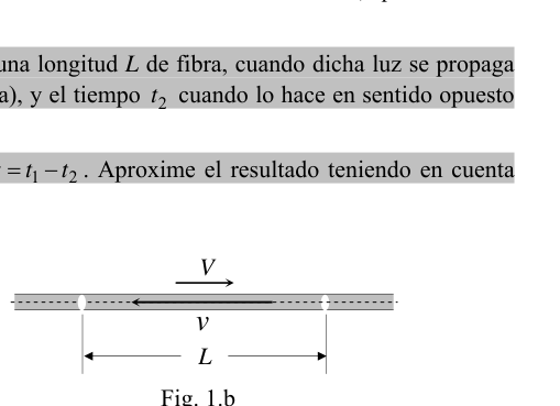 Fig. 1a–1b: light in moving fiber, both directions
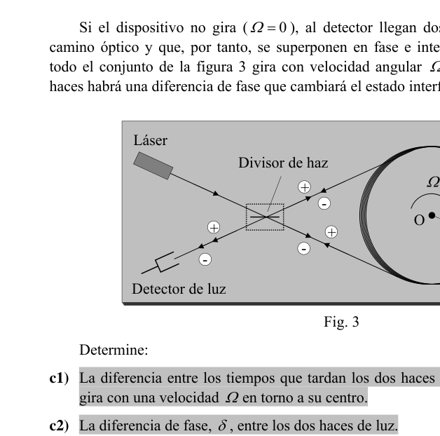 Fig. 2a–2b: light in rotating circular fiber ring
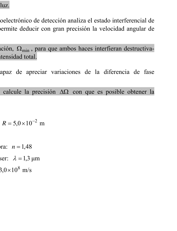 Fig. 3: fiber optic gyroscope schematic with coil
Topic: Wave Optics, Special Relativity, Oscillations & Waves Metodi: Interference & Diffraction Analysis, Approximation & Series Expansion, Superposition Principle Competenze: Mathematical Modeling, Physical Reasoning Objects: Coil Fonte: Testo (PDF) — p.1
P3. Il giroscopo di fibra ottica interferenziale
Un giroscopo meccanico è un apparato consistente in un disco che ruota rapidamente su un asse libero che, a causa della conservazione del momento angolare, tende a rimanere in una direzione costante. È stato inventato dal fisico francese Jean Bernard Léon Foucault (1819-1868) ed è usato di solito per mantenere l’orientamento nello spazio, in particolare per la stabilizzazione del percorso di navi, aerei e satelliti. Ma ci sono altri dispositivi non meccanici, più precisi, versatili e semplici, che vengono utilizzati per lo stesso fine.
Anche il fisico francese Georges Sagnac scoprì nel 1911 che “una onda elettromagnetica che si muove in un percorso chiuso è influenzata dalla velocità angolare del sistema”. Basandosi sul cosiddetto “effetto Sagnac”, a partire dal 1960 iniziò l’utilizzo dei giroscopi ottici, che derivarono nel 1970 nei giroscopi interferenziali di fibra ottica. In questo esercizio vengono descritti in modo semplificato questi giroscopi.
Come esercizio preliminare, si consideri che un raggio laser di lunghezza d’onda (in vuoto) si diffonda a velocità da una fibra ottica rettilinea, con un indice di refraczione efficace , che si muove longitudinalmente a velocità .
Nota: L’indice di refraczione efficace si riferisce alla velocità di avanzamento della luce lungo l’asse della fibra, , dove è la velocità della luce nel vuoto.
**a1) ** Determina il tempo che la luce impiega per percorrerne una lunghezza di fibra, quando tale luce si diffonde nella stessa direzione in cui la fibra si muove (Fig. 1a), e il tempo quando lo fa in senso opposto (Fig. 1b).
**a2) ** Determina la differenza tra questi due tempi, . Approcciare il risultato tenendo conto che .
Considera ora che la fibra ottica si curva in una circonferenza di lunghezza , e che ruota a velocità angolare attorno al suo centro in senso orario. Tra la fibra si diffondono due fasci di luce in direzioni opposte.
**b) ** Determina la differenza tra i tempi e che la luce impiega per percorrere l’anello circolare di lunghezza in senso orario e antiorario, rispettivamente (Fig. 2a y 2b). Esprimere il risultato in funzione dell’area dell’anello.
Il funzionamento di un giroscopo a fibra ottica è schematizzato in Fig. 3. Il 50% della luce emessa dal laser si riflette nel divisore del fascio (+), attraversa spirate circolari di fibra in senso orario e, dopo essere riflessa nel divisore del fascio, colpisce il rilevatore. L’altro 50% della luce viene trasmessa attraverso il divisore di fascio (−), attraversa gli spirati in senso antiorario e incide sul rilevatore dopo essere stata trasmessa attraverso il divisore.
Se il dispositivo non gira (), al rilevatore arrivano due fasci coerenti che hanno percorso la stessa via ottica e che si superpongono in fase e interferiscono costruttivamente. Tuttavia, quando l’intero insieme della Fig. 3 gira a velocità angolare intorno al centro delle spirale, tra i due fasci ci sarà una differenza di fase che cambierà lo stato di interferenza nel sensore (effetto Sagnac). Determina:
**c1) ** La differenza tra i tempi impiegati dai due fasci per raggiungere il rilevatore, , quando il dispositivo ruota a una velocità intorno al suo centro.
**c2) ** La differenza di fase, , tra i due fasci di luce.
Nei giroscopi a fibra ottica, il sistema di rilevamento optoelettronica analizza lo stato di interferenza dei due fasci, determina questa differenza di fase e consente di dedurre con grande precisione la velocità angolare di rotazione e, di conseguenza, i cambiamenti di direzione.
**d) ** Determina la velocità angolare minima di rotazione, , in modo che entrambi i fasci interferiscano distruttivamente nel rilevatore, in modo da annullare l’intensità totale.
Supponiamo che il sistema di rilevamento sia in grado di rilevare variazioni della differenza di fase .
**e) ** Con i dati riportati di seguito calcola la precisione con cui è possibile ottenere la velocità angolare di rotazione.
- Radiospirazione di fibra ottica:
- Numero di spirale:
- Indice di rifrazione efficace della fibra:
- L’onda di lunghezza (in vuoto) del laser:
- Velocità della luce in vuoto:
Fig. 1a1b: light in moving fiber, both directions
Fig. 2a2b: light in rotating circular fiber ring
Fig. 3: fibra ottica gyroscope schematic with coil
Topic: Wave Optics, Special Relativity, Oscillations & Waves Metodi: Interference & Diffraction Analysis, Approximation & Series Expansion, Superposition Principle Competenze: Mathematical Modeling, Physical Reasoning Objects: Coil Fonte: Testo (PDF) — p.1
P3. The optical fiber interference gyroscope
A mechanical gyroscope is a device consisting of a disc that rotates rapidly on a free axis that, due to the conservation of angular momentum, tends to stay in a constant direction. It was invented by French physicist Jean Bernard Léon Foucault (1819-1868) and is commonly used to maintain orientation in space, particularly for the stabilization of the course of ships, aircraft and satellites. But there are other non-mechanical devices, more precise, versatile and simple, that are used for the same purpose.
The French physicist Georges Sagnac also discovered in 1911 that “an electromagnetic wave moving in a closed path is influenced by the angular velocity of the system”. Based on the so-called “Sagnac effect”, from 1960 onwards the use of optical gyroscopes began, which were derived in 1970 into fiber optic interference gyroscopes. This exercise describes these gyroscopes in a simplified way.
As a preliminary exercise, consider that a laser beam of wavelength (in vacuum) is propagated at a speed by a straight-line optical fiber with an effective refractive index , moving longitudinally at a speed .
Note: The effective refractive index refers to the speed of light advancing along the fiber axis, , where is the speed of light in vacuum.
**a1) ** Determine the time it takes for light to travel a length of fibre when it propagates in the same direction as the fibre moves (Fig. 1a), and when doing so in the opposite direction (Fig. 1b).
**a2) ** Determine the difference between these two times, . Approach the result taking into account that .
Consider now that the optical fiber is curved at a circumference of length , and that it rotates at angular speed around its center in a clockwise direction. Two beams of light propagate in opposite directions through the fiber.
**b) ** Determine the difference between the and time taken by light to travel the circular ring of length in clockwise and counterclockwise directions, respectively (Fig. 2a y 2b). Express the result according to the area of the ring.
The operation of a fiber optic gyroscope is outlined in Fig. 3. 50% of the light emitted by the laser is reflected in the beam divider (+), passes through circular spirals of fibre clockwise and, after reflecting in the beam divider, hits the detector. The other 50% of the light is transmitted through the beam divider (−), passes through the spirals in the anti-hour direction and hits the detector after being transmitted through the divider.
If the device does not rotate (), two coherent beams that have traveled the same optical path reach the detector and are therefore overlapping in phase and constructively interfere. However, when the whole set of Fig. 3 spins at angular speed around the center of the spirals, between the two beams there will be a phase difference that will change the interference state in the detector (Sagnac effect). Determine:
**c1) ** The difference between the times it takes the two beams to reach the detector, , when the device rotates at a speed around its center.
**c2) ** The phase difference, , between the two beams of light.
In fibre optic gyroscopes, the optoelectronic detection system analyses the interference state of the two beams, determines this phase difference and allows the angular rotation speed and, consequently, the change in direction to be deduced with great precision.
**d) ** Determine the minimum angular rotation speed, , so that both beams interfere destructively with the detector, thus canceling out the total intensity.
Suppose the detection system is capable of detecting variations in the phase difference .
**e) ** Calculate the precision with which the angular rotation speed can be obtained with the data given below.
- Radius of the optical fibre spirals:
- Number of springs:
- Effective refractive index of the fibre:
- Wavelength (in vacuum) of the laser:
- Light speed in vacuum:
The Commission shall adopt implementing acts in accordance with Article 21 of Regulation (EC) No 1272/2009. 1a1b: light in moving fiber, both directions*
The Commission shall adopt implementing acts in accordance with Article 21 of Regulation (EC) No 1272/2009. 2a2b: light in rotating circular fiber ring*
The Commission shall adopt implementing acts in accordance with Article 21 of Regulation (EC) No 1272/2009. The following information shall be provided:
Topic: Wave Optics, Special Relativity, Oscillations & Waves Metodi: Interference & Diffraction Analysis, Approximation & Series Expansion, Superposition Principle Competenze: Mathematical Modeling, Physical Reasoning Objects: Coil Fonte: Testo (PDF) — p.1