P3. Oscilador electromagnético
El circuito que se muestra en la figura contiene dos rieles metálicos paralelos separados por una distancia , que están sujetos sobre una mesa horizontal no conductora. Cada riel tiene una longitud , una resistencia eléctrica total y su resistividad es uniforme a lo largo del riel. Sus extremos están conectados a las dos baterías ideales (sin resistencia interna) de la figura, de fuerza electromotriz cada una, mediante cables de resistencia despreciable.
a) Determine la intensidad que circula por el circuito.
Se coloca ahora encima de los rieles y perpendicularmente a ellos la barra metálica homogénea (de color rojo en la figura), de masa y resistencia , de forma tal que puede deslizarse a lo largo de los rieles sin fricción. A continuación se estudiarán los circuitos y , y los nodos y .
b) Demuestre que cuando la barra está en el centro, a una distancia de (es decir, con ), se anula la intensidad que circula por ella.
c) Determine las resistencias y del circuito , así como las y del circuito , cuando la barra está desplazada una distancia de .
d) Obtenga la intensidad en el caso en que la barra está desplazada una distancia de .
e) Muestre que para despreciable la intensidad es proporcional al desplazamiento , , y determine la constante en función de , , y .
Se aplica ahora un campo magnético uniforme perpendicular al plano del circuito (apuntando hacia fuera del papel como ejemplo en la figura).
f) Indique el efecto del campo magnético sobre la barra cuando éste: i) apunta hacia fuera del papel como en la figura, y ii) cuando apunta hacia dentro.
g) Obtenga la aceleración de la barra causada por el campo magnético y, en el caso en que se produzcan pequeñas oscilaciones, determine su periodo. Trabaje con la expresión genérica si no obtuvo el valor de en el apartado e).
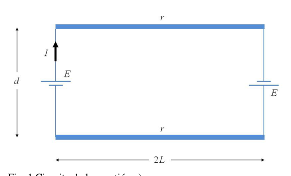 Circuit with two rails and batteries
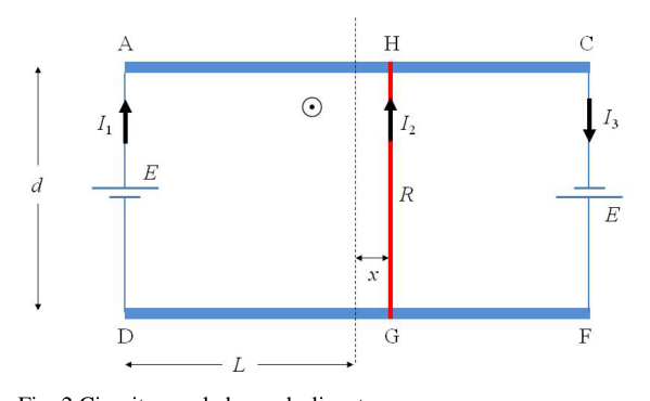 Circuit with sliding conducting bar HG
Topic: Circuits, Electromagnetic Induction, Oscillations & Waves Metodi: Kirchhoff’s Laws, Lorentz Force Analysis, Simple Harmonic Motion Analysis Competenze: Physical Reasoning, Mathematical Modeling Objects: Battery, Rod Fonte: Testo (PDF) — p.1
P3. Oscillatore elettromagnetico
Il circuito mostrato nella figura contiene due binari metallici paralleli separati da una distanza , che sono collegati su un tavolo orizzontale non conduttore. Ogni rail ha una lunghezza , una resistenza elettrica totale e la sua resistività è uniforme lungo il rail. I suoi estremi sono collegati alle due batterie ideali (senza resistenza interna) della figura, di forza elettromotrice ciascuna, mediante cavi di resistenza scarsa.
a) Determina l’intensità che circola nel circuito.
Si colloca ora sopra i binari e perpendicolare a essi la barra metallica omogenea (rossa nella figura), di massa e resistenza , in modo da poter scivolare lungo i binari senza attrito. I circuiti e e i nodi e saranno studiati.
b) Dimostra che quando la barra è al centro, a una distanza di (cioè con ), l’intensità che circola attraverso la barra viene annullata.
c) Determina le resistenze e del circuito , nonché e del circuito , quando la barra è spostata a distanza di .
d) Ottenere l’intensità nel caso in cui la barra sia spostata a distanza di .
e) Mostrare che per scarsa l’intensità è proporzionale al spostamento , , e determinare la costante in funzione di , , e .
Ora viene applicato un campo magnetico uniforme perpendicolare al piano del circuito (indicando fuori dalla carta come esempio nella figura).
f) Indicare l’effetto del campo magnetico sulla barra quando: (i) punta fuori dalla carta come nella figura e (ii) punta dentro.
g) Ottenere l’accelerazione della barra causata dal campo magnetico e, nel caso di piccole oscillazioni, determinare il suo periodo. Lavorare con l’espressione generica se non ha ottenuto il valore di in paragrafo e).
Circuito con due rails e batterie
Circuito con sliding conducting bar HG
Topic: Circuits, Electromagnetic Induction, Oscillations & Waves Metodi: Kirchhoff’s Laws, Lorentz Force Analysis, Simple Harmonic Motion Analysis Competenze: Physical Reasoning, Mathematical Modeling Objects: Battery, Rod Fonte: Testo (PDF) — p.1
**P3. The following table shows the results of the calculations:
The circuit shown in the figure contains two parallel metal rails separated by a distance , which are held on a non-conducting horizontal table. Each rail has a length , a total electrical resistance and its resistance is uniform throughout the rail. Its ends are connected to the two ideal batteries (without internal resistance) of the figure, of electromotive force each, by means of scornful resistance cables.
(a) Determine the intensity of the circuit.
The homogeneous metal bar (red in figure) of mass and resistance is now placed above the rails and perpendicular to them, so that it can slide along the rails without friction. The following circuits and and the nodes and shall be studied.
(b) Demonstrate that when the bar is in the centre, at a distance from (i.e. with ), the intensity circulating through it is cancelled.
(c) Determine the and resistance of the circuit as well as the and resistance of the circuit when the bar is moved a distance of .
(d) Get the intensity in the case where the bar is moved a distance of .
(e) Show that for negligible the intensity is proportional to the displacement , , and determine the constant based on , , and .
A uniform magnetic field perpendicular to the plane of the circuit is now applied (pointing out of the paper as an example in the figure).
(f) Indicate the effect of the magnetic field on the bar when it: (i) points outwards from the paper as shown in the figure, and (ii) points inwards.
(g) Find the acceleration of the bar caused by the magnetic field and, in the event of small oscillations, determine its period. Work with the generic expression if you did not obtain the value of in paragraph (e).
Circuit with two rails and batteries
Circuit with sliding conducting bar HG
Topic: Circuits, Electromagnetic Induction, Oscillations & Waves Metodi: Kirchhoff’s Laws, Lorentz Force Analysis, Simple Harmonic Motion Analysis Competenze: Physical Reasoning, Mathematical Modeling Objects: Battery, Rod Fonte: Testo (PDF) — p.1