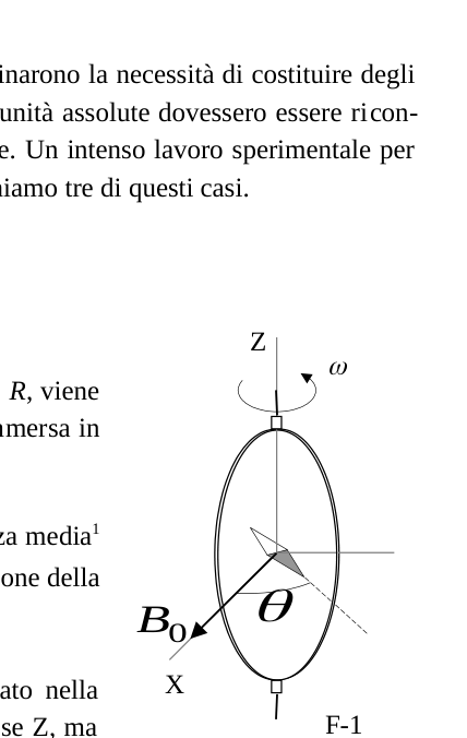
- (0.5+1.0) Calcolare la forza elettromotrice indotta nella bobina e la potenza media1 necessaria per mantenere la bobina in moto. Trascurare l’autoinduzione della bobina. Un piccolo ago magnetico è collocato al centro della bobina, come mostrato nella Figura F-1. Esso è libero di ruotare lentamente in un piano orizzontale intorno all’asse Z, ma non è in grado di seguire la rapida rotazione della bobina.
p.1 — Bobina rotante con ago magnetico, assi Z e X
Topic: Electromagnetic Induction, Magnetism, Rotational Dynamics Metodi: Faraday’s Law of Induction, Energy Conservation Method, Calculus-Integration Competenze: Mathematical Modeling, Physical Reasoning Objects: Coil, Magnet Fonte: Testo (PDF) — p.1
- (0.5+1.0) Calculate the induced electromotive force in the coil and the mean power1 necessary to keep the coil running. The self-induction of the The coil. A small magnetic needle is placed in the center of the coil, as shown in F-1 figure. It is free to rotate slowly in a horizontal plane around the Z-axis, but It is unable to follow the rapid rotation of the coil.
**p.1 ** Rotating coil with magnetic needle, Z and X axes
Topic: Electromagnetic Induction, Magnetism, Rotational Dynamics Metodi: Faraday’s Law of Induction, Energy Conservation Method, Calculus-Integration Competenze: Mathematical Modeling, Physical Reasoning Objects: Coil, Magnet Fonte: Testo (PDF) — p.1
- (2.0) Una volta raggiunto il regime stazionario, l’ago si dispone lungo una direzione che forma un piccolo angolo con . Calcolare la resistenza R della bobina in funzione di questo angolo e degli altri parametri del sistema. Lord Kelvin usò questo metodo negli anni 1860 per stabilire lo standard assoluto dell’ohm. Per evitare la bobina rotante, Lorenz progettò il metodo alternativo, in seguito usato da Lord Rayleigh e Ms. Sidgwick, che analizziamo nei prossimi paragrafi. Determinazione dell’ “ohm” (Rayleigh, Sidgwick). L’apparato sperimentale è mostrato in Figura F-2. Esso è formato da due dischi di metallo identici D e D’ di raggio b fissati su un’asta conduttrice SS’. Un motore fa ruotare il dispositivo ad una velocità angolare , che può essere regolata per misurare R. Due bobine identiche C e C’ (di raggio a e aventi ciascuna N spire) sono poste attorno ai dischi. Esse sono collegate in modo che la corrente I vi scorra in versi opposti. L’intero apparato serve per misurare la resistenza R. 1 Il valore medio di una grandezza , periodica di periodo T, è dato da Possono essere utili uno o più dei seguenti integrali: , , e anche Th 2 - Pagina 1 di 3 R.S.E.F. G D’ 4 C’ C’ ’ S’ S F-2 D’ 1 2
R I 3 X Z F-1 0 B 36th Olimpiade Internazionale di Fisica. Salamanca (Spagna) 2005
Topic: Electromagnetic Induction, Magnetism, Circuits Metodi: Faraday’s Law of Induction, Small-Angle Approximation, Torque & Angular Momentum Analysis Competenze: Mathematical Modeling, Physical Reasoning Objects: Coil, Disk, Galvanometer Fonte: Testo (PDF) — p.1
- (2.0) Once stationary, the cage is arranged in a direction that forms a small angle with . Calculate the coil resistance R according to this angle and other system parameters. Lord Kelvin used this method in the 1860s to establish the absolute standard of ohm. To avoid the rotating coil, Lorenz designed the alternative method, later used by Lord Rayleigh and Ms. Sidgwick, which we will discuss in the following paragraphs. Determination of the ohm (Rayleigh, Sidgwick). The experimental apparatus is shown in Figure F-2. It is consisting of two identical metal discs D and D’ of radius b They’re fixed on an SS’s lead. A motor makes the device at an angular velocity , which can be adjusted for measuring R. Two identical coils C and C’ (of radius a and with each N spire) are placed around the The discs. They are connected so that the current I It flows in opposite directions. The whole apparatus is used for measuring resistance R. 1 Average value of a size , periodic period T, is given by One or more of the following integers may be useful: , , and also Th 2 - Page 1 of 3 R.S.E.F. G D’ 4 C’ C’ ’ S’ S F-2 D’ 1 2
R I 3 X Z F-1 0 B 36th International Olympics in physics. The Commission shall adopt delegated acts in accordance with Article 21 of Regulation (EC) No 1290/2005.
Topic: Electromagnetic Induction, Magnetism, Circuits Metodi: Faraday’s Law of Induction, Small-Angle Approximation, Torque & Angular Momentum Analysis Competenze: Mathematical Modeling, Physical Reasoning Objects: Coil, Disk, Galvanometer Fonte: Testo (PDF) — p.1
- (2.0) Assumere che la corrente I che scorre nelle bobine C e C’ produca nelle regioni che contengono rispettivamente D e D’ un campo magnetico uniforme B uguale a quello esistente al centro della bobina. Calcolare2 la forza elettromotrice indotta tra i contatti 1 e 4, nel caso in cui la distanza tra le bobine sia molto maggiore del loro raggio ed anche a >> b. I dischi sono collegati al circuito attraverso contatti striscianti nei punti 1 e 4. Il galvanometro G misura la corrente che scorre nel circuito 1-2-3-4.
Topic: Electromagnetic Induction, Magnetism, Circuits Metodi: Lorentz Force Analysis, Ampère’s Law, Calculus-Integration Competenze: Mathematical Modeling, Diagrammatic Reasoning Objects: Coil, Disk, Galvanometer Fonte: Testo (PDF) — p.2
- (2.0) Assume that current I flowing in coils C and C produces in regions containing D and D respectively a uniform magnetic field B equal to that existing in the centre of the coil. Calculate the induced electromotive force between contact points 1 and 4 in the case where the distance between the coils is much greater than their contact points radius and also a >> b. The discs are connected to the circuit by means of crawling contacts in points 1 and 4. The G galvanometer measures the current which It flows in the 1-2-3-4 circuit.
Topic: Electromagnetic Induction, Magnetism, Circuits Metodi: Lorentz Force Analysis, Ampère’s Law, Calculus-Integration Competenze: Mathematical Modeling, Diagrammatic Reasoning Objects: Coil, Disk, Galvanometer Fonte: Testo (PDF) — p.2
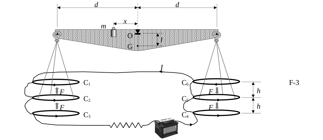
- (0.5) La resistenza R è misurata quando G segna zero. Esprimere R in funzione dei parametri fisici del sistema. Determinazione dell’ “ampere” Facendo scorrere una corrente in due conduttori e misurando la forza tra loro si ottiene una determinazione assoluta della corrente stessa. La “bilancia per correnti” progettata da Lord Kelvin nel 1882 sfrutta questo metodo. La bilancia è fornita di sei spire identiche C6 di raggio a, collegate in serie. Come mostrato in Figura F-3, le spire C1, C3, C4 e C6 sono fissate su due piani orizzontali separati da una piccola distanza 2h. Le spire C2 e C5 invece sono appese ai bracci della bilancia di lunghezza d; all’equilibrio esse sono equidistanti da entrambi i piani. La corrente I scorre nelle varie spire in verso tale che la forza magnetica su C2 sia diretta verso l’alto, mentre quella su C5 sia diretta verso il basso. Quando la corrente scorre attraverso il circuito, è necessario disporre una massa m a distanza x dal fulcro O, per ristabilire la posizione d’equilibrio della bilancia descritta precedentemente.
Topic: Electromagnetic Induction, Circuits, Magnetism Metodi: Faraday’s Law of Induction, Kirchhoff’s Laws, Physical Modeling Competenze: Mathematical Modeling, Physical Reasoning Objects: Coil Fonte: Testo (PDF) — p.2
- (0.5) The resistance R is measured when G is zero. Express R in terms of the physical parameters of the system. Determination of the ampere By running a current in two conductors and measuring the force between them, an absolute determination of the current itself. The balance for currents designed by Lord Kelvin in 1882 uses this method. The balance sheet is provided by: six identical C6 spires of radius a, connected in series. As shown in Figure F-3, the C1, C3, C4 and C6 spires are fixed on two horizontal planes separated by a short distance of 2 h. The C2 and C5 windings are hinged on the arms of the balance of the length d; at equilibrium they are equidistant from both planes. The current I flows in the various spirals in such a way that the magnetic force on C2 is directed upwards, while that on C5 It’s downward. When the current flows through the circuit, you have to have a mass m at a distance x from the The balance sheet balance sheet is set at the same time as the balance sheet balance sheet balance sheet.
Topic: Electromagnetic Induction, Circuits, Magnetism Metodi: Faraday’s Law of Induction, Kirchhoff’s Laws, Physical Modeling Competenze: Mathematical Modeling, Physical Reasoning Objects: Coil Fonte: Testo (PDF) — p.2
- (1.0) Calcolare la forza F agente su C2 dovuta all’interazione magnetica con C1. Per semplicità assumere che la forza per unità di lunghezza sia uguale a quella che si avrebbe fra due fili rettilinei indefiniti percorsi da correnti parallele.
p.2 — Bilancia per correnti con spire C1-C6
Topic: Magnetism, Newtonian Mechanics Metodi: Ampère’s Law, Free-Body Diagram, Approximation & Series Expansion Competenze: Mathematical Modeling, Physical Reasoning Objects: Coil, Wire Fonte: Testo (PDF) — p.2
- (1.0) Calculate the force F agent on C2 due to the magnetic interaction with C1. The Commission has already adopted a proposal for a regulation on the force per unit length equal to that which would be between two strands of continuous straight lines running through currents parallel to the other.
C1-C6 torque leverage
Topic: Magnetism, Newtonian Mechanics Metodi: Ampère’s Law, Free-Body Diagram, Approximation & Series Expansion Competenze: Mathematical Modeling, Physical Reasoning Objects: Coil, Wire Fonte: Testo (PDF) — p.2
- (1.0) La corrente I viene misurata quando la bilancia si trova in equilibrio. Esprimere l’espressione di I in funzione dei parametri fisici del sistema. Le dimensioni dell’apparato sono tali per cui è possibile trascurare gli effetti delle spire di destra su quelle di sinistra e viceversa. Sia M la massa della bilancia (senza considerare la massa m e quelle trascurabili delle parti appese ai bracci), G il suo centro di massa e l la distanza
Topic: Magnetism, Rigid Body Statics, Circuits Metodi: Torque & Angular Momentum Analysis, Free-Body Diagram, Ampère’s Law Competenze: Mathematical Modeling, Diagrammatic Reasoning Objects: Coil Fonte: Testo (PDF) — p.2
- (1.0) Current I is measured when the balance is in balance. Express the expression of I in the function of the system’s physical parameters. The size of the apparatus is such that it is possible to overlook the The effects of the right-handed spires on the left-handed spires and vice versa. Whether M the mass of the balance (without considering the mass m and negligible parts hanging from the arms), G its mass The mass center and the distance
Topic: Magnetism, Rigid Body Statics, Circuits Metodi: Torque & Angular Momentum Analysis, Free-Body Diagram, Ampère’s Law Competenze: Mathematical Modeling, Diagrammatic Reasoning Objects: Coil Fonte: Testo (PDF) — p.2
- (2.0) L’equilibrio della bilancia è stabile rispetto a spostamenti che producono piccoli cambiamenti dell’altezza di C2 e per C5. Calcolare2 il massimo valore per cui la bilancia ritorna verso la posizione di equilibrio quando viene lasciata libera. CODICE DEL PAESE CODICE DELLO STUDENTE NUMERO DI PAGINA NUMERO TOTALE DI PAGINE 2 Si consideri che i centri delle spire rimangono approssimativamente allineati. Usare le approssimazioni o per , e per piccoli . Th 2 - Pagina 2 di 3 R.S.E.F. x m d C1 C2 C3 h h F F F F d O G C6 C5 C4 l F-3 I 36th Olimpiade Internazionale di Fisica. Salamanca (Spagna) 2005 Problema Teorico n. 2 – FOGLIO RISPOSTE Domanda Formule e idee fondamentali utilizzate Risultati in forma analitica Punti 1
1.5 2 R = 2.0 3
2.0 4 R = 0,5 5 F = 1.0 6 I = 1.0 7
2.0 Th 2 - Pagina 3 di 3 R.S.E.F.
Topic: Rotational Dynamics, Magnetism, Newtonian Mechanics Metodi: Torque & Angular Momentum Analysis, Small-Angle Approximation, Approximation & Series Expansion Competenze: Mathematical Modeling, Physical Reasoning Objects: Coil Fonte: Testo (PDF) — p.2
- (2.0) The balance sheet balance is stable with small changes in the balance sheet. the height of C2 and for C5. Calculate the maximum value The balance sheet is returned to the position of balance when it’s left unattended. The country code The Student Code Page number Total number of pages 2 It is considered that the centers of the spires remain approximately aligned. Use of approximations o for , e For little ones . Th 2 - Page 2 of 3 R.S.E.F. x m d C1 C2 C3 h h F F F F d O G C6 C5 C4 l F-3 I 36th International Olympics in physics. The Commission shall adopt delegated acts in accordance with Article 21 of this Regulation. Theoretical problem n. 2 Answered Question by Mr. Basic formulas and ideas used Results in analytical form Points 1
1.5 2 R = 2.0 3
2.0 4 R = 0,5 5 F = 1.0 6 I = 1.0 7
2.0 Th 2 - Page 3 of 3 R.S.E.F.
Topic: Rotational Dynamics, Magnetism, Newtonian Mechanics Metodi: Torque & Angular Momentum Analysis, Small-Angle Approximation, Approximation & Series Expansion Competenze: Mathematical Modeling, Physical Reasoning Objects: Coil Fonte: Testo (PDF) — p.2