n-esima spira
1 Risposte e risultati
Quando è sospesa, la molla giocattolo si allunga per il suo stesso peso e per quello dell’eventuale carico di rondelle; gli allungamenti delle singole spire decrescono dall’alto verso il basso al diminuire del peso che fa da forza di trazione. Quando la molla è scarica le spire più in basso, circa una decina, restano unite senza allungarsi.1
Conviene contare le spire prima di deformare l’ultima per fare il gancio, come viene consigliato nel testo; si può apprezzare fino a 1⁄4 o 1/5 di spira. Il numero totale delle spire servirà poi per trovare la massa della molla.
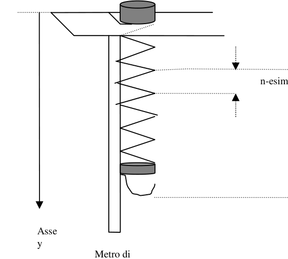
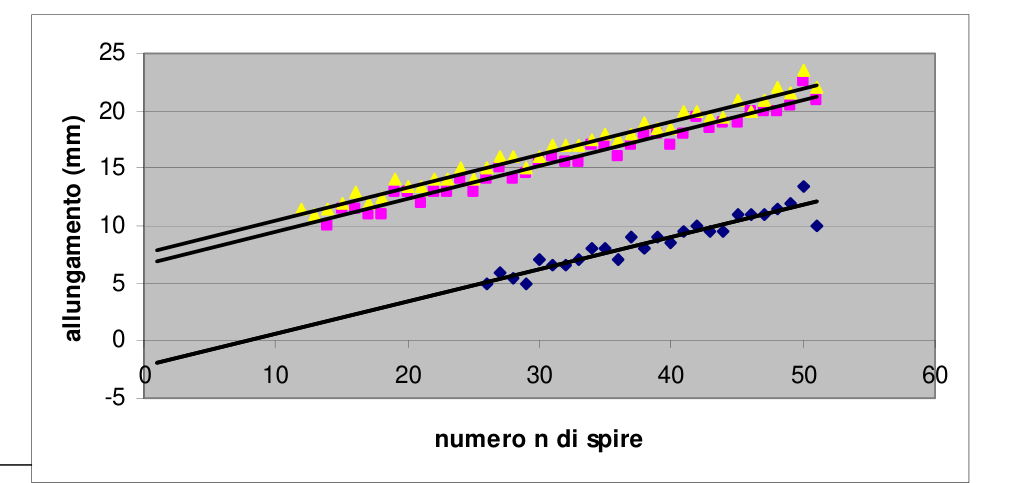
- Ricava sperimentalmente la funzione = f (n) , dove è la lunghezza assunta in direzione verticale dalla singola n-esima spira a molla scarica, ed n è il numero di spire sottostanti (vedi figura 1). Quando la molla è appesa, il punto finale del gancio dovrebbe essere sulla stessa verticale dell’inizio della prima spira, se si vuole avere un numero intero di spire in sospensione. Sul metro di carta fissato al righello, che pende verticalmente lungo la molla a contatto con le spire, si legge la posizione y di ogni singola spira, o meglio la posizione del punto di ogni spira che risulti allineato con il punto d’inizio della prima, per esempio là dove questa si stacca dal righello di sostegno, oppure con un altro punto scelto come riferimento. Si leggono le posizioni y delle spire della molla scarica. La figura suggerisce di numerare le spire a partire dal basso e di comprendere nelle n spire anche quella che si deforma, e il cui è in esame. esprime l’allungamento della spira sommato al suo spessore. La tabella I riporta alcuni risultati per una molla di massa 103,62 g (misurata con bilancia), e 87,5 spire. Si è apprezzato il 1⁄2 millimetro. Si può procedere costruendo il grafico degli allungamenti di una singola spira in funzione delle spire sottostanti. Il comportamento della molla sembra molto regolare, ma i punti risultano un po’ dispersi, anche perché non si possono apprezzare variazioni della lunghezza inferiori a 0,5 mm. Comunque il grafico appare chiaramente rettilineo e se ne può ricavare l’equazione = A0 + B0 n. È molto più comodo ottenere una regressione lineare con la calcolatrice. Il grafico rettilineo per la molla scarica non passa per l’origine, e attraversa l’asse delle ascisse in un punto corrispondente a no spire (una decina di spire). Difatti le spire più basse della molla non si deformano per effetto del loro peso. L’equazione della retta esprime la relazione fisica tra numero di spire e allungamento solo per n> no . Per n no , con la formula si otterrebbero valori negativi o nulli, mentre in realtà ogni corrisponde al solo spessore s di una spira (s = lunghezza molla / numero totale di spire) . La funzione = f (n) è: per 0 < n n0, = s ; per n0 < n nmax, = A0 + B0 n
Esempio: n0 = 11 ; lunghezza molla = 50 mm, numero totale di spire = 87,5; s = 0,57 mm per 0 < n 11, = 0,57 mm per 11 < n nmax, = A0 + B0 n , con A0 = -3,72 mm - 3,7 mm , B0 = 0,332 mm (da grafico manuale) A0 = - 2,56 mm -2,6 mm , B0 = 0,301 mm (da calcolatrice)
Il termine con incertezza maggiore è A0.
1 Nel processo di fabbricazione di alcune molle, tutte le spire vengono “ritorte” in maniera che stiano unite le une alle altre: quindi, per staccare le spire occorre una certa forza , che in gergo si chiama forza di pretensione. In questo caso, qualunque sia la sua origine, questa forza di precompressione equivale al peso di una decina di spire. n spire n-esima spira Metro di carta Figura 1 Asse y
2 Tabella I
con bilancia: massa di 12 rondelle 1 = 38,2 g; massa di 12 rondelle 2 = 42,7 g; massa molla = 103,62 g Numero n di spire y Scarica (mm) y (rondelle1) (mm) y (rondelle2) (mm)
scarica. (mm) (rondelle 1) (mm) (rondelle 2) (mm)
Incert.(mm) 0,5 0,5 0,5
1 1 1 51 0 0 0
50 10 21 22
10 21 22
49 23,5 43,5 45,5
13,5 22,5 23,5
48 35,5 64 67
12 20,5 21,5
47 47 84 89
11,5 20 22
46 58 104 110
11 20 21
45 69 124 130
11 20 20
44 80 143 151
11 19 21
43 89,5 162 170,5
9,5 19 19,5
42 99 180,5 190
9,5 18,5 19,5
41 109 200 210
10 19,5 20
40 118,5 218 230
9,5 18 20
39 127 235 248,5
8,5 17 18,5
38 136 253 267
9 18 18,5
37 144 271 286
8 18 19
36 153 288 304
9 17 18
35 160 304 321,5
7 16 17,5
34 168 321 339,5
8 17 18
33 176 338 357
8 17 17,5
32 183 353,5 374
7 15,5 17
31 189,5 369 391
6,5 15,5 17
30 196 385 408
6,5 16 17
29 203 400,5 424
7 15,5 16
28 208 415 439
5 14,5 15
27 213,5 429 455
5,5 14 16
26 219,5 444 471
6 15 16
25 224,5 458 486
5 14 15
24
471 500
13 14
23
485 515
14 15
22
498 529
13 14
21
511 543
13 14
20
523 556,5
12 13,5
19
536 570
13 13,5
18
549 584
13 14
17
560 596,5
11 12,5
16
571 608,5
11 12
15
582,5 621,5
11,5 13
14
594 633,5
11,5 12
13
604 645
10 11,5
12
656
11
11
667,5
11,5
Determina la massa della molla con la minor incertezza possibile. Esempio di risultati per una molla di massa 103,62 g (misurata con bilancia), e 87,5 spire. Si è apprezzato 1⁄2 millimetro.
Procedura (I):
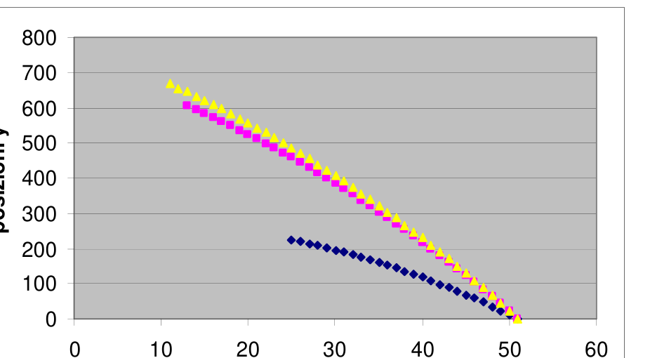
Dalle posizioni y si ricavano le lunghezze (= allungamento + spessore) di ogni singola spira, oppure di gruppetti di spire consecutive (p.es. 5 spire) sia per molla scarica che per molla caricata con 12 rondelle Si costruiscono con gli stessi assi i
3 due grafici delle lunghezze in funzione del numero n di spire sottostanti e la figura suggerisce come contare queste ultime, così da avere lunghezze crescenti al crescere di n. Raggruppando più spire (p.es. 5) si ottiene una minore dispersione dei punti. I due grafici sono rettilinei e (circa) paralleli tra loro. La molla non sembra presentare isteresi; si può supporre che a parità di allungamento di una singola spira o di un gruppo di spire, la forza di trazione sulla spira sia la stessa. Per ogni valore di allungamento, tra i due numeri di spire corrispondenti nei due grafici c’è una differenza, che è dovunque la stessa se i grafici sono paralleli, e che esprime il numero di spire che pesano come le dodici rondelle. Le spire appaiono tutte uguali per forma, dimensioni e materiale, e quindi dal numero complessivo di spire della molla si ricava facilmente quanto pesa tutta la molla.
Esempio2 con le rondelle di “tipo 1”. Massa rondelle 1 = 38,2 0,1 g; numero totale di spire = 87,5 0,25 spire Dai grafici manuali vs n) : n scarica - n carica = 30 2 spire Valore della massa molla = 38,2 87,5 / 30 = 111,42 g Incertezza % = 0,26% + 0,29% + 6,67% = 7,22 % massa molla = 111 7 g
Dai grafici della lunghezza complessiva di 5 spire consecutive in funzione di n, l’incertezza del valore di (n scarica - n carica) diminuisce e così quella sulla massa: n scarica - n carica = 31,8 0,6 spire massa molla = 105 2 g
Oppure con la calcolatrice si fanno le due regressioni lineari di in funzione di n. Dai coefficienti delle relazioni = A1
- B1 n e = A0 + B0 n , con molla carica e scarica, si può ricavare la differenza tra le ascisse n a parità di . Il risultato è unico se le rette sono parallele, cioè se B1 =B0 .
Esempio. Molla scarica : A0 = -2,5627 ; B0 = 0,30115 Molla carica con rondelle di tipo 1: A1 = 6,8088 ; B1 = 0,28864 (Molla carica con rondelle di tipo 2 e 3; A2 = 7,9126 ; B2 = 0,2880; A3 = 7,157 ; B3 = 0,3037)
I due coefficienti angolari B risultano un po’ diversi per molla carica e non. Facendo il conto con coefficiente angolare massimo B0 e poi co
p.1 — Molla giocattolo sospesa con metro e spire
p.3 — Grafico allungamento in funzione del numero di spire
p.4 — Grafico posizioni y in funzione delle spire
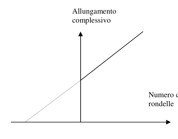
p.4 — Schema allungamento complessivo contro numero rondelle
Topic: Newtonian Mechanics, Elasticity & Materials, Oscillations & Waves Metodi: Hooke’s Law, Graph Linearization, Experimental Data Analysis, Error Propagation Competenze: Graph Linearization, Experimental Data Analysis, Error Propagation Objects: Spring Fonte: Testo (PDF) — p.1 Soluzione: Soluzioni (PDF)
n-esima spira
1 Responsibilities and Results
When it’s suspended, it springs The toy stretches out for his the same weight and for that The following information shall be provided: The following are the main features of the The individual spirals decrease From top to bottom decrease in weight the force of traction. When the The spring is discharged the spires more in low, about a dozen, remain The two are joined without stretching.1
It’s better to count the spires first. The first is to deform the latter to make the Hook, as recommended The Commission has already taken a number of measures to ensure that the a quarter or a fifth of a spire. Total number of spires It’ll be used to find the mass of the spring.
- Experimentally, the function = f (n) is obtained, where is the length taken vertically by the single n-eighth discharge spring, and n is the number of underlying spires (see Figure 1). When the spring is suspended, the end point of the hook should be on the same vertical as the start of the first spindle, if He wants to have a whole number of expired expirations. On the paper meter fixed to the reel, which hangs vertically along the If the spinning is in contact with the spins, the position y of each individual spinning is read, or rather the position of the point of each spinning that It is aligned with the starting point of the first, for example where it is detached from the supporting reel, or with a other point chosen as a reference. You read the y-positions of the exhaust spring’s spires. The figure suggests that The number of spires from the bottom and including the one that is deformed and whose is under consideration in the n spires. The length of the spire is expressed as the length of the spire plus its thickness. Table I shows some results for a spring of mass 103,62 g (measured by weight) and 87,5 spires. It was appreciated by the It’s a millimeter. The graph of the elongations of a single spire can be constructed according to the underlying spires. Il The spring’s behavior seems very regular, but the spots are a little bit missing, also because you can’t appreciate variations in length less than 0,5 mm. However, the graph appears clearly straight and you can ricavare l’equazione = A0 + B0 n. It’s much more convenient to get a linear regression with the calculator. The straight graph for the discharge spring does not pass through the source, and crosses the axis of the axis at a point corresponding to Not a ten-horse. In fact, the lower spires of the spring do not deform by their weight. The equation The number of lines of the line expresses the physical relationship between number of turns and elongation only by n> no. For n no, with the formula si They would get negative or zero values, whereas in reality each corresponds to the single thickness s of a spire (s = spring length) / total number of spires) The function = f (n) is: for 0 < n n0, = s; for n0 < n nmax, = A0 + B0 n
Example: n0 = 11; spring length = 50 mm, total number of spires = 87,5; s = 0,57 mm For 0 < n 11, = 0,57 mm for 11 < n nmax, = A0 + B0 n , with A0 = -3,72 mm - 3,7 mm , B0 = 0,332 mm (manual chart) A0 = - 2,56 mm -2,6 mm , B0 = 0,301 mm (by calculator)
The term with greater uncertainty is A0.
1 In the manufacture of some springs, all the spires are re-worked so that the ends are joined to the ends of the spires. Other things: so, to unwind the spires, you need a certain force, which in slang is called force of pretence. In this case, Whatever its origin, this precompression force is equal to the weight of a dozen spires. Notwithstanding the provisions of this Article, N-third spiral Metro of paper The following is the list of the following: Other axes y
2 The following table shows the following:
with weight: mass of 12 round 1 = 38,2 g; mass of 12 round 2 = 42,7 g; mass of spring = 103,62 g Number n di Breathing y Downloading (mm) y (round1) (mm) y (round 2) (mm)
- It’s off. (mm) (Rounds 1) (mm) (Rounds 2) (mm)
The following is the list of the official languages of the European Union: 0,5 0,5 0,5
1 1 1 51 0 0 0
50 10 21 22
10 21 22
49 23,5 43,5 45,5
13,5 22,5 23,5
48 35,5 64 67
12 20,5 21,5
47 47 84 89
11,5 20 22
46 58 104 110
11 20 21
45 69 124 130
11 20 20
44 80 143 151
11 19 21
43 89,5 162 170,5
9,5 19 19,5
42 99 180,5 190
9,5 18,5 19,5
41 109 200 210
10 19,5 20
40 118,5 218 230
9,5 18 20
39 127 235 248,5
8,5 17 18,5
38 136 253 267
9 18 18,5
37 144 271 286
8 18 19
36 153 288 304
9 17 18
35 160 304 321,5
7 16 17,5
34 168 321 339,5
8 17 18
33 176 338 357
8 17 17,5
32 183 353,5 374
7 15,5 17
31 189,5 369 391
6,5 15,5 17
30 196 385 408
6,5 16 17
29 203 400,5 424
7 15,5 16
28 208 415 439
5 14,5 15
27 213,5 429 455
5,5 14 16
26 219,5 444 471
6 15 16
25 224,5 458 486
5 14 15
24
471 500
13 14
23
485 515
14 15
22
498 529
13 14
21
511 543
13 14
20
523 556,5
12 13,5
19
536 570
13 13,5
18
549 584
13 14
17
560 596,5
11 12,5
16
571 608,5
11 12
15
582,5 621,5
11,5 13
14
594 633,5
11,5 12
13
604 645
10 11,5
12
656
11
11
667,5
11,5
Determine the mass of the spring with the least possible uncertainty. Example of results for a spring of mass 103,62 g (measured by weight), and 87,5 spires. It’s been appreciated a millimeter.
The following procedure (I):
From the y positions the lengths (= elongation + thickness) of each individual spire or of groups of spires are obtained The following is the list of the following: 5 spires) for both the discharge spring and the spring loaded with 12 cylinders
3 two graphs of length according to the number n of underlying spires and the figure suggests how to count these ultime, così da avere lunghezze crescenti al crescere di n. By grouping multiple spires (e.g. 5) a minor is obtained scattering of the dots. The two graphs are straight and (almost) parallel to each other. The spring does not appear to be hysterical; it can be assumed that at the same length as a single spiral or a group of spirals the force of traction on the spire is the same. For each elongation value, between the two corresponding spire numbers So there’s a difference in the two graphs, which is the same everywhere if the graphs are parallel, and that expresses the number of spins that They weigh like the twelve swords. The spires all look the same in shape, size and material, and so by the number of spires, The total of the springs is easily collected as the whole spring weighs.
Example2 with type 1 roundings. The weight of the round 1 = 38,2 0,1 g; total number of spires = 87,5 0,25 spires From the manual graph vs n) : n discharge - n load = 30 2 spires The weight of the spring = 38,2 87,5 / 30 = 111,42 g Uncertainty % = 0,26% + 0,29% + 6,67% = 7,22% of the mass of the spring = 111 7 g
From the overall length graphs of 5 consecutive spires in function of n, the uncertainty of the value of (n discharge - n charge) decreases and so does the mass: n scarica - n carica = 31,8 0,6 spire massa molla = 105 2 g
Or with the calculator, you do the two linear regressions of as a function of n. From the coefficients of the relations = A1
- B1 n and = A0 + B0 n , with spring load and discharge, the difference between the n axes can be obtained at . Il The result is unique if the lines are parallel, that is, if B1 = B0.
I’ll give you an example. The following is the list of the following: Loaded bag with type 1: A1 = 6,8088; B1 = 0,28864 (Low load with type 2 and type 3 swirls; A2 = 7,9126; B2 = 0,2880; A3 = 7,157; B3 = 0,3037)
The two angular coefficients B are slightly different for charge and not. By calculating with the maximum angular coefficient B0 and then co
p.1 — Molla giocattolo sospesa con metro e spire
p.3 Extension chart according to the number of spires
**p.4 ** Graph of positions y by spires
p.4 — Schema allungamento complessivo contro numero rondelle
Topic: Newtonian Mechanics, Elasticity & Materials, Oscillations & Waves Metodi: Hooke’s Law, Graph Linearization, Experimental Data Analysis, Error Propagation Competenze: Graph Linearization, Experimental Data Analysis, Error Propagation Objects: Spring Fonte: Testo (PDF) — p.1 Soluzione: Soluzioni (PDF)