PROBLEMA n. 1 – Tre cilindri molto scivolosi (100 Punti)
In figura a sinistra sono rappresentati schematicamente tre cilindri uguali, ciascuno di massa , posti su un piano orizzontale con le basi verticali e complanari e in modo che ciascun cilindro abbia la superficie laterale tangente a quelle degli altri due. I cilindri sono molto scivolosi dato che ogni forma di attrito fra tutte le superfici a contatto è trascurabile. Allora, per mantenere in equilibrio la struttura, vengono tese, una da una parte e una dall’altra – come si vede in figura –, due corde inestensibili e di massa trascurabile che collegano gli assi dei due cilindri appoggiati sul piano.
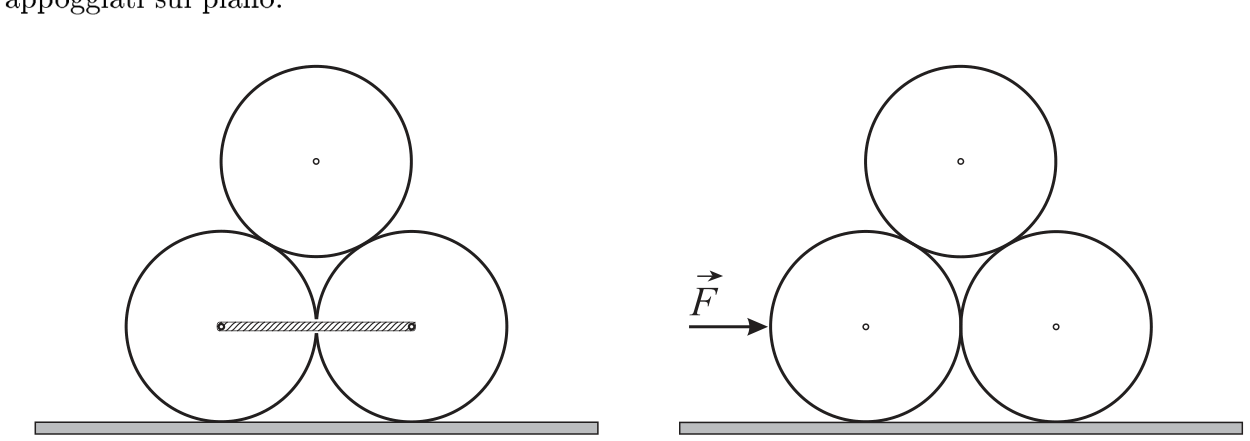
- Qual è la minima tensione in ciascuna corda che consente di mantenere in equilibrio il sistema?
In seguito si mette in moto il sistema applicando, al cilindro di sinistra, una forza , orizzontale, come mostrato nella figura a destra, e subito dopo si eliminano le corde.
- Qual è l’intervallo di valori che può assumere la forza che accelera il sistema senza che la struttura collassi?
Topic: Newtonian Mechanics, Rigid Body Statics Metodi: Free-Body Diagram, Vector Decomposition, Symmetry Argument Competenze: Diagrammatic Reasoning, Mathematical Modeling, Physical Reasoning Objects: Cylinder, String Fonte: Testo (PDF) — p.1 Soluzione: Soluzioni (PDF)
PROBLEM no. 1 – Three Very Slippery Cylinders (100 Points)
In the figure on the left, three identical cylinders are schematically represented, each of mass , placed on a horizontal plane with their bases vertical and coplanar, arranged so that each cylinder has its lateral surface tangent to those of the other two. The cylinders are very slippery because any form of friction between all contacting surfaces is negligible. To maintain the structure in equilibrium, two inextensible and massless ropes are pulled—one from one side and one from the other—as shown in the figure—connecting the axes of the two cylinders resting on the plane.
- What is the minimum tension in each rope that allows maintaining equilibrium of the system?
Subsequently, the system is set into motion by applying to the leftmost cylinder a horizontal force , as shown in the figure on the right, and immediately after removing the ropes.
- What is the range of values that the force accelerating the system can assume without causing the structure to collapse?
Solution: Soluzioni (PDF)
PROBLEMA n. 2 – Tri-ciclo…termodinamico (35 Punti)
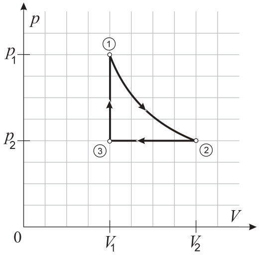
La figura rappresenta un ciclo termodinamico cui è sottoposto un sistema di moli di un gas perfetto monoatomico.
Il volume del gas è inizialmente raddoppiato mediante una trasformazione isoterma quasi statica 1–2, e successivamente viene riportato al valore iniziale con una compressione isobara quasi statica 2–3. Infine, con un riscaldamento durante il quale il volume rimane costante, il sistema viene riportato allo stato iniziale.
- Calcolare il rendimento di un’ipotetica macchina termica che segua questo ciclo termodinamico.
Topic: Thermodynamics Metodi: First Law of Thermodynamics, Thermodynamic Cycle Analysis, Ideal Gas Law Competenze: Mathematical Modeling, Physical Reasoning Objects: Gas, Heat Engine Fonte: Testo (PDF) — p.1 Soluzione: Soluzioni (PDF)
PROBLEM no. 2 – Tri-cycle…thermodynamic (35 Points)
The figure shows a thermodynamic cycle to which a system of moles of a perfect monatomic gas is subjected.
The volume of the gas is initially doubled through a quasi-static isothermal transformation 1–2, and subsequently returned to its initial value via a quasi-static isobaric compression 2–3. Finally, by heating during which the volume remains constant, the system is brought back to its initial state.
- Calculate the efficiency of a hypothetical heat engine that follows this thermodynamic cycle.
Solution: Soluzioni (PDF)
PROBLEMA n. 3 – Prove di elasticità (100 Punti)
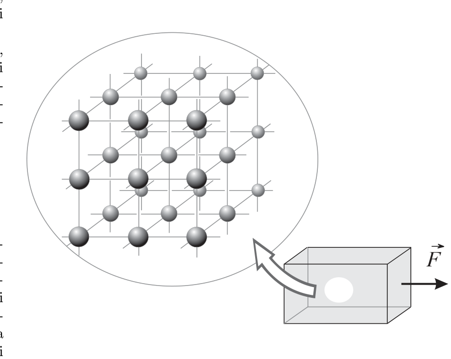
In questo problema si vuole studiare, con un modello semplificato, l’elasticità di un materiale cristallino. Supponiamo di avere un materiale che, in assenza di forze esterne, è costituito di un reticolo cubico di atomi, che interagiscono con un’energia potenziale interatomica che, al variare della distanza interatomica , ha questa forma:
con ; . Per semplicità, si consideri soltanto l’interazione di ciascun atomo con i suoi vicini più prossimi; si trascuri quindi l’interazione fra gli atomi che si trovano agli estremi di una diagonale del reticolo. Questa è una semplificazione piuttosto drastica perché è proprio l’interazione coi secondi vicini che tiene insieme il solido.
- Si traccino, in modo qualitativo e in funzione della distanza interatomica , il grafico dell’energia potenziale e quello della relativa forza di interazione tra gli atomi vicini che può essere dedotto dal primo.
- Si dica quanto vale la distanza di equilibrio fra gli atomi, e a quali distanze la forza risulta attrattiva o repulsiva.
Applicando ad una faccia del cristallo una forza di trazione perpendicolare ad un piano reticolare, mentre la faccia opposta è fissata ad un supporto, il cristallo si deforma, allungandosi nella direzione della forza. Sia il modulo della forza, l’area della superficie a cui la forza è applicata, la lunghezza del cristallo nella direzione della forza, e il suo allungamento per effetto della forza applicata.
Si chiama “sforzo” la grandezza e “deformazione” l’allungamento relativo . Il rapporto tra queste due grandezze, per piccole deformazioni, è costante ed è una caratteristica del materiale nota come “modulo di Young”:
Si calcoli:
- il modulo di Young del materiale;
- la deformazione quando il solido è al punto di rottura;
- lo sforzo necessario per giungere alla rottura.
Nota: Può essere utile ricordare che quando .
Topic: Elasticity & Materials, Newtonian Mechanics Metodi: Stress-Strain Analysis, Hooke’s Law, Calculus-Integration, Approximation & Series Expansion Competenze: Mathematical Modeling, Diagrammatic Reasoning, Physical Reasoning Objects: Atom Fonte: Testo (PDF) — p.2 Soluzione: Soluzioni (PDF)
PROBLEM no. 3 – Elasticity Tests (100 Points)
In this problem, a simplified model is used to study the elasticity of a crystalline material.
We suppose that in the absence of external forces, the material consists of a cubic lattice of atoms which interact via an interatomic potential energy that, as a function of the interatomic distance , has this form:
with ; .
For simplicity, only the interaction of each atom with its nearest neighbors is considered; thus, interactions between atoms located at opposite ends of a lattice diagonal are neglected. This is a rather drastic simplification, since it is precisely the interaction with second nearest neighbors that holds the solid together.
-
Draw, in a qualitative manner and as a function of the interatomic distance , the graph of the potential energy and that of the corresponding interatomic force between neighboring atoms , which can be deduced from the first.
-
State what is the equilibrium distance between atoms, and for which distances the force becomes attractive or repulsive.
By applying a tensile force perpendicular to a crystal plane, while the opposite face is fixed to a support, the crystal deforms by elongating in the direction of the force. Let be the magnitude of the force, the area of the surface to which the force is applied, the length of the crystal in the direction of the force, and the elongation caused by the applied force.
The quantity is called “stress”, and the relative elongation is called “strain”. The ratio between these two quantities, for small deformations, is constant and represents a material property known as the “Young’s modulus”:
Compute:
- the Young’s modulus of the material;
- the strain when the solid is at the point of fracture;
- the stress required to reach fracture.
Note: It may be useful to recall that when .
Solution: Soluzioni (PDF)
PROBLEMA n. 4 – Condensatori sempre più piccoli (65 Punti)
La capacità di un condensatore in cui lo spessore del dielettrico sia molto piccolo rispetto alle dimensioni delle armature (la condizione può essere posta come , essendo la superficie delle armature) può essere sempre calcolata come quella di un condensatore a facce piane e parallele.
- Dopo aver determinato l’espressione della capacità di un condensatore sferico nel vuoto () le cui armature abbiano raggi e , verificare la precedente affermazione, quando sia soddisfatta la condizione .
Si consideri ora un condensatore (per il quale la condizione detta sia verificata, cosicché possa essere assimilato ad un condensatore piano) in cui metà del volume sia costituito dalle armature e metà dal materiale isolante caratterizzato dalla costante dielettrica relativa () e dalla rigidità dielettrica () definita come il massimo campo elettrico che il dielettrico può sopportare senza che venga attraversato – e quindi distrutto – da una scarica.
Un condensatore è a sua volta individuato da due parametri caratteristici: la capacità e la tensione massima di lavoro .
N.B. Per non confondere la tensione, cioè la d.d.p. applicata tra le armature con il volume del condensatore, quest’ultimo sarà indicato – in modo inusuale – con la lettera .
-
Mostrare che il volume di un condensatore di capacità e tensione massima di lavoro , non può essere inferiore ad un minimo. Trovare in funzione delle due proprietà caratteristiche del dielettrico e .
-
Quali dei seguenti materiali dielettrici consentirebbe di produrre condensatori di volume minimo?
| Materiale | [kV/mm] | |
|---|---|---|
| 1. Carta paraffinata | 2.5 | 50 |
| 2. Ceramica | 60 | 15 |
| 3. Mica | 8 | 90 |
| 4. Polistirolo | 2.6 | 50 |
| 5. Porcellana | 6 | 25 |
| 6. Resina epossidica | 4 | 35 |
| 7. Teflon | 2.2 | 20 |
NOTA: I dati riportati in tabella sono puramente indicativi e in alcuni casi si riferiscono a particolari campioni dei diversi materiali; per esempio vari tipi di resine o di ceramiche possono avere caratteristiche notevolmente diverse da quelle indicate qui.
- Tra quelli riportati sopra, quale dielettrico si può ritenere sia stato usato per realizzare un condensatore da che supporta una tensione di lavoro di ed ha la forma di un piccolo parallelepipedo di ?
Materiale prodotto dal gruppo
Segreteria Olimpiadi Italiane della Fisica presso Liceo Scientifico “U. Morin”, MESTRE (VE) fax: 041.584.1272 e-mail: olifis@libero.it
Topic: Electrostatics Metodi: Gauss’s Law, Electric Potential Method, Experimental Data Analysis Competenze: Mathematical Modeling, Physical Reasoning, Estimation & Approximation Objects: Capacitor Fonte: Testo (PDF) — p.3 Soluzione: Soluzioni (PDF)
PROBLEM no. 4 – Ever-smaller Capacitors (65 Points)
The capacitance of a capacitor in which the thickness of the dielectric is very small compared to the dimensions of the plates (the condition may be stated as , with being the surface area of the plates) can always be calculated as that of a parallel-plate capacitor.
- After having determined the expression for the capacitance of a spherical capacitor in vacuum () whose plates have radii and , verify the previous statement when the condition is satisfied.
Now consider a capacitor (for which the aforementioned condition holds, so that it may be regarded as a parallel-plate capacitor) in which half the volume is occupied by the plates and half by an insulating material characterized by a relative permittivity () and dielectric strength (), defined as the maximum electric field that the dielectric can withstand without being punctured—and thus destroyed—by a discharge.
A capacitor is in turn identified by two characteristic parameters: the capacitance and the maximum operating voltage .
N.B. To avoid confusion between the voltage, i.e., the potential difference applied across the plates, and the volume of the capacitor, the latter will be indicated—uncommonly—with the letter .
-
Show that the volume of a capacitor with capacitance and maximum operating voltage , cannot be less than a minimum value. Find as a function of the two dielectric’s characteristic properties and .
-
Which of the following dielectric materials would allow for the production of capacitors with minimum volume?
| Material | [kV/mm] | |
|---|---|---|
| 1. Paraffined paper | 2.5 | 50 |
| 2. Ceramic | 60 | 15 |
| 3. Mica | 8 | 90 |
| 4. Polystyrene | 2.6 | 50 |
| 5. Porcelain | 6 | 25 |
| 6. Epoxy resin | 4 | 35 |
| 7. Teflon | 2.2 | 20 |
NOTE: The data reported in the table are purely indicative and, in some cases, refer to particular samples of different materials; for example, various types of resins or ceramics may have characteristics significantly different from those indicated here.
- Among those listed above, which dielectric material could be considered to have been used in the fabrication of a capacitor with capacitance , able to withstand an operating voltage of , and having the shape of a small rectangular prism measuring ?
Material produced by the group
Secretariat of the Italian Physics Olympiad
at Liceo Scientifico “U. Morin”, MESTRE (VE)
fax: 041.584.1272 e-mail: olifis@libero.it
Soluzione: Soluzioni (PDF)