Velocità della luce E1
Page 1 of 10
Attenzione: Tutti i risultati delle misure e dei valori calcolati devono essere riportati nelle unità del SI con l’appropriato numero di cifre significative. Le incertezze sperimentali vanno determinate solo quando viene esplicitamente richiesto.
1.0 Introduzione Esperimenti con un misuratore laser di distanza (LDM)
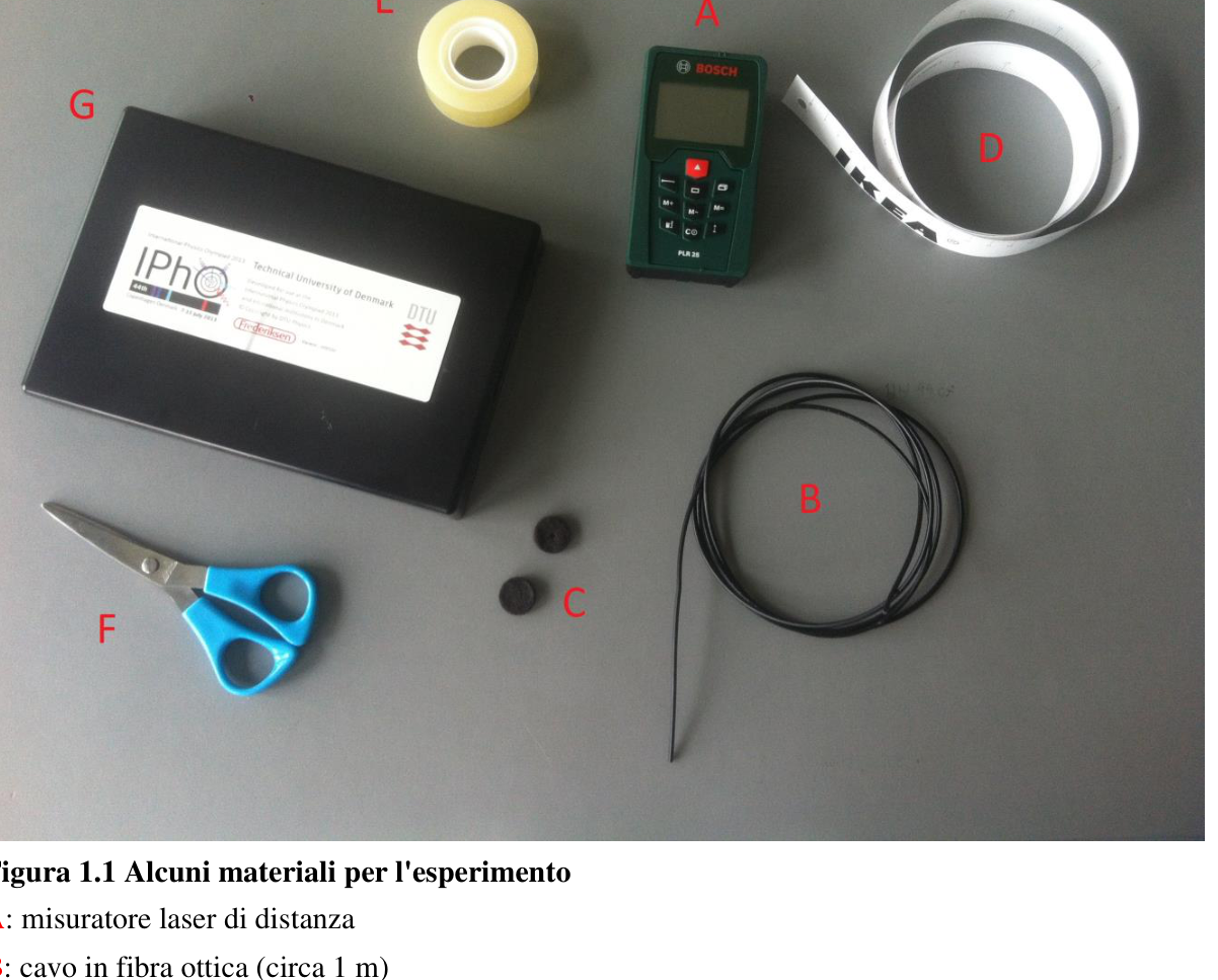
Figura 1.1 Alcuni materiali per l’esperimento A: misuratore laser di distanza B: cavo in fibra ottica (circa 1 m) C: feltrini neri autoadesivi con un foro D: metro di carta E: nastro adesivo F: forbici G: coperchio della scatola nera Un misuratore laser di distanza (LDM, vedi Fig. 1.2 e Fig. 1.3) consiste di un emettitore e un ricevitore. L’emettitore è un diodo laser che emette un fascio laser modulato, cioè un fascio laser la
Velocità della luce E1
Page 2 of 10
cui ampiezza varia con una frequenza molto alta. Quando il raggio laser urta un oggetto, la luce è riflessa in tutte le direzioni dalla macchia del laser. Una parte della luce ritorna al ricevitore dello strumento che è posizionato immediatamente accanto all’emettitore. L’ottica dello strumento è focalizzata sulla macchia del laser e riceve la luce di ritorno da essa emessa. L’elettronica dello strumento misura la differenza temporale nella modulazione del segnale luminoso ricevuto rispetto a quello emesso. Il ritardo della modulazione è esattamente il tempo che impiega la luce per andare dall’emettitore al ricevitore. Il tempo misurato è quindi convertito in distanza y attraverso la formula
Questo valore di è mostrato sullo schermo dello strumento. Qui è la velocità della luce. La costante dipende dalla configurazione dello strumento; sullo strumento è possibile scegliere se misurare la distanza dal retro o dalla fronte dello strumento. Quando il misuratore laser di distanza viene acceso, esso è predisposto per misurare la distanza dal retro. Questa configurazione deve essere mantenuta durante tutte le misure. A causa dell’errore di parallasse il LDM non può misurare una distanza minore di 5 cm. La distanza massima che può essere misurata è circa 25 m. La forma dello strumento è tale che sia la parte posteriore sia quella frontale sono perpendicolari al fascio laser. Quando lo strumento è appoggiato sul tavolo, la polarizzazione è verticale (perpendicolare allo schermo). Il laser a diodo è di classe 2 con una potenza inferiore a 1 mW e lunghezza d’onda 635 nm. L’incertezza sulla misura, indicata dal produttore, è mm. Attenzione: Il laser a diodo dello strumento può danneggiare la vista. Non guardare nel fascio laser e non proiettarlo negli occhi delle altre persone!
Configurazione del LDM La formula precedente per la distanza presuppone che la luce si propaghi con velocità . Per il livello di accuratezza dell’esperimento non è necessario distinguere tra la velocità della luce nel vuoto e in aria, poiché l’indice di rifrazione per aria secca a pressione atmosferica e temperatura ambiente vale .
Velocità della luce E1
Page 3 of 10
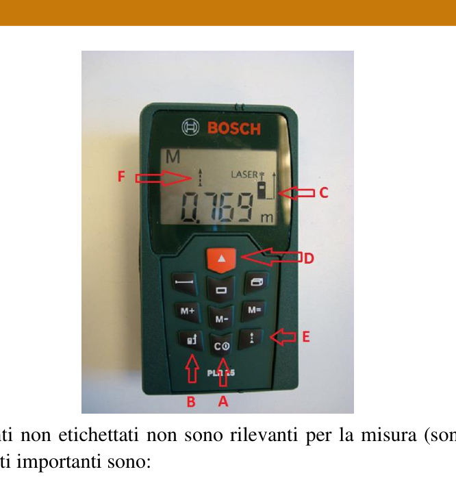
Figura 1.2 I sei pulsanti non etichettati non sono rilevanti per la misura (sono usati per calcolare aree e volumi). I pulsanti importanti sono: A: on/off B: interruttore per alternare la misurazione dal retro o dal davanti dello strumento C: indicatore della misura fronte/retro D: accensione del laser / inizio della misura E: misura continua F: indicatore di misura continua
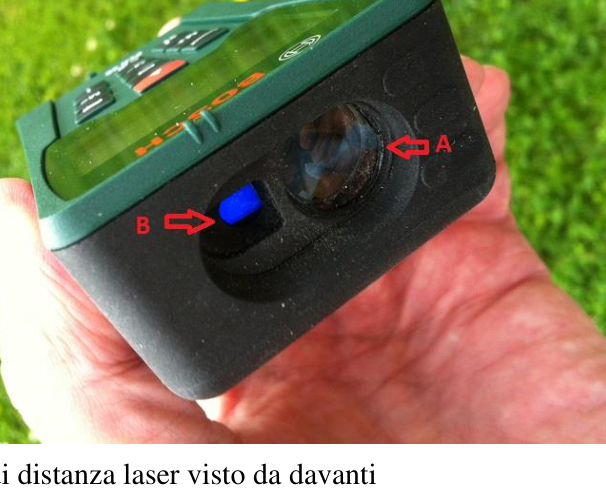
Figura 1.3 Il misuratore di distanza laser visto da davanti A: ricevitore: ottica focalizzata sulla macchia del laser B: emettitore: non guardare nel fascio laser!
Velocità della luce E1
Page 4 of 10
1.1 Misura con un misuratore laser di distanza Lo strumento effettuerà una misura premendo il pulsante D, vedi Fig. 1.2.
1.1a Usa il LDM per misurare la distanza dalla cima del tavolo al pavimento. Indica l’incertezza sperimentale . Mostra con un disegno come effettui la misura. 0.4
Velocità della luce E1
Page 5 of 10
1.2 Esperimento con un cavo a fibra ottica
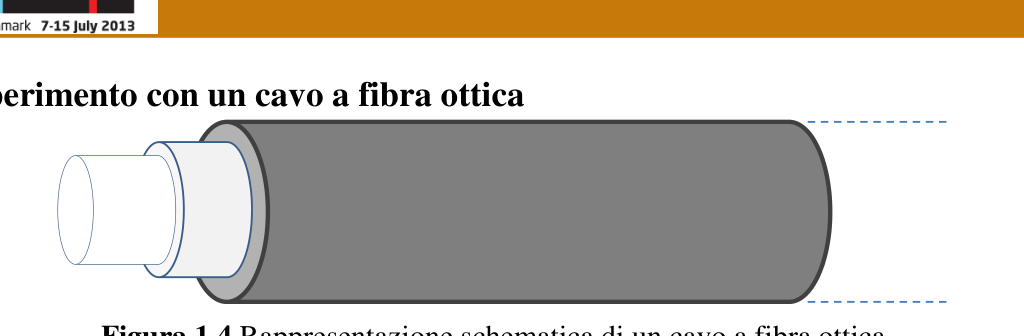
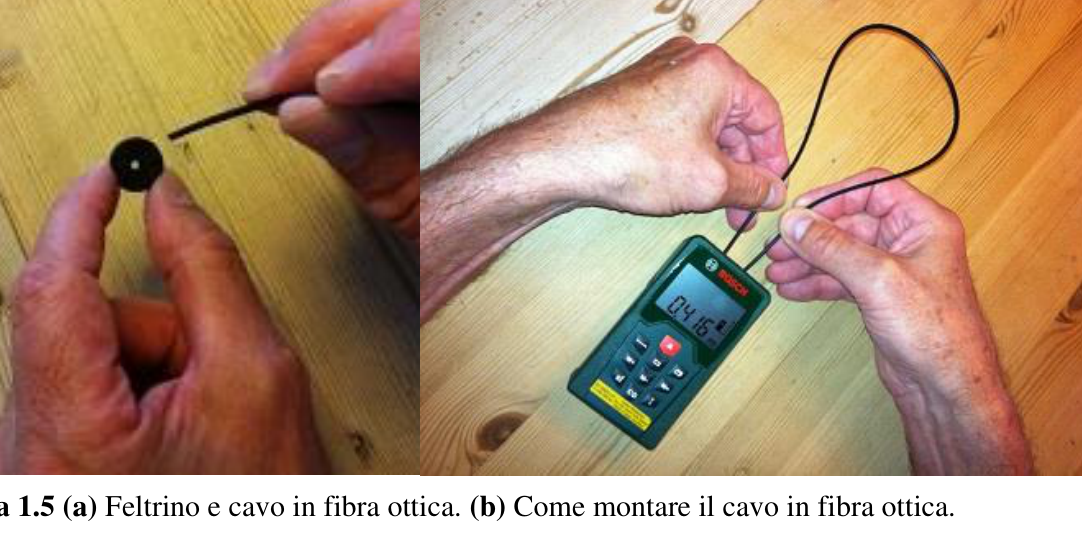
Figura 1.4 Rappresentazione schematica di un cavo a fibra ottica. Ti è stato dato un cavo a fibra ottica di lunghezza approssimativa di 1 m e diametro approssimativo di 2 mm. Il cavo consiste di due materiali ottici. Quello al centro (di diametro approssimativo di 1 mm) è costituito da un materiale plastico con alto indice di rifrazione. Esso è circondato da un materiale di rivestimento costituito da un diverso materiale plastico con un indice di rifrazione leggermente minore, il quale è rivestito da uno strato protettivo di plastica nera. Il materiale centrale e quello di rivestimento fungono da guida d’onda per la luce immessa nel cavo. Infatti l’interfaccia tra i due provoca una riflessione totale che impedisce alla luce di lasciare il materiale centrale. Ciò accade finché l’angolo di incidenza è maggiore dell’angolo limite per la riflessione totale. La luce pertanto rimarrà dentro al materiale centrale della fibra, anche nel caso in cui la fibra sia curvata, purché non lo non sia eccessivamente. Il LDM deve ora essere configurato per una misurazione continua (pulsante E, vedi Fig. 1.2), cosicché l’indicazione sul display di si aggiorna approssimativamente una volta al secondo. Il LDM si spegnerà automaticamente dopo alcuni minuti. Può essere riattivato premendo il pulsante rosso di avvio. Con attenzione e delicatamente copri l’ottica del ricevitore del LDM con un feltrino nero (l’altro è di riserva) in cui è stato praticato un foro di diametro 2 mm (vedi A Fig. 1.3). Il lato adesivo del feltrino deve essere premuto con delicatezza contro la lente. Inserisci un cavo a fibra ottica di lunghezza nel foro del feltrino così da fargli toccare l’ottica del rivelatore, vedi Fig. 1.5.
Figura 1.5 (a) Feltrino e cavo in fibra ottica. (b) Come montare il cavo in fibra ottica.
Velocità della luce E1
Page 6 of 10
L’altro estremo del cavo deve essere tenuto contro l’emettitore, in modo tale che quest’ultimo tocchi la fibra nel mezzo del fascio laser. Ora leggi il valore di dallo strumento. Le forbici messe a disposizione devono essere utilizzate per tagliare il cavo in fibra ottica a lunghezze differenti . Attenzione: pensa e pianifica molto attentamente il taglio del cavo in fibra ottica, poiché non te ne verrà consegnato dell’altro!! Nota anche che il display del LDM potrebbe mostrare l’icona di un termometro dopo un po’ di tempo di funzionamento in modalità continua a causa del surriscaldamento dell’elettronica. In questo caso spegni il LDM per un certo tempo per raffreddare lo strumento.
1.2a Misura i valori corrispondenti di e . Riporta i tuoi valori in una tabella. Traccia un grafico di in funzione di . 1.8 1.2b Usa il grafico per trovare l’indice di rifrazione del materiale centrale della fibra ottica. Calcola la velocità della luce nel materiale centrale della cavo a fibra ottica. 1.2
Velocità della luce E1
Page 7 of 10
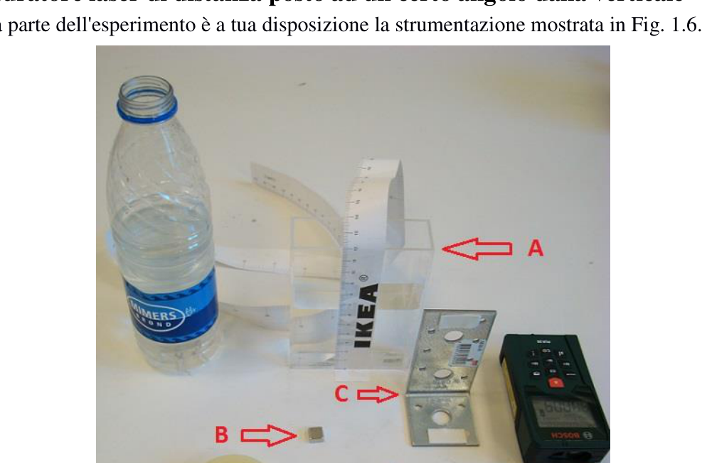
1.3 Misuratore laser di distanza posto ad un certo angolo dalla verticale In questa parte dell’esperimento è a tua disposizione la strumentazione mostrata in Fig. 1.6.
Figura1.6 Strumentazione mostrata nella figura: A: recipiente per esperimenti di ottica con acqua e metro di carta B: magnete per fissare il profilo di ferro angolato in cima alla scatola nera. (Il magnete si trova attaccato al profilo di ferro angolato.) C: profilo di ferro angolato con fascetta autoadesiva D: fascetta autoadesiva
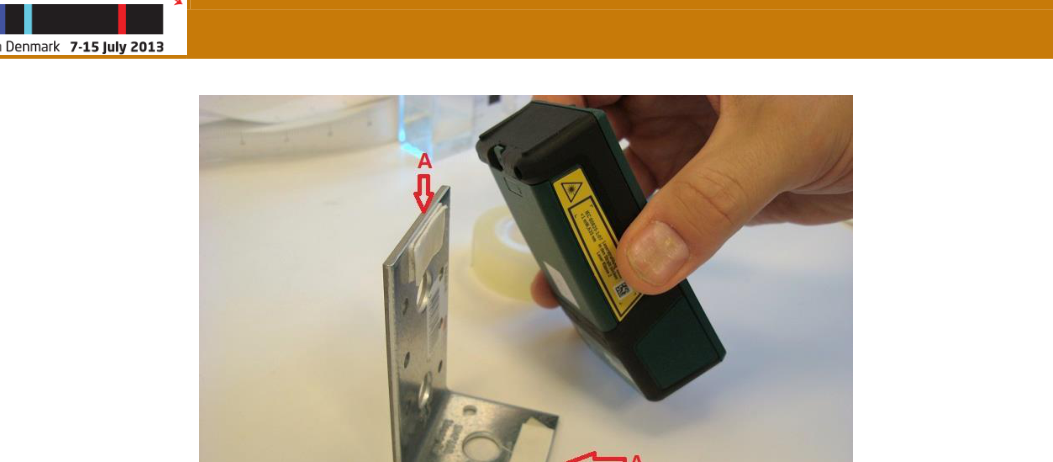
Rimuovi il tampone di feltro nero dalla lente. Il LDM va montato nel modo seguente: fissa due fascette autoadesive sul profilo di ferro angolato come si vede nella figura 1.7, nel punto A.
Velocità della luce E1
Page 8 of 10
Figura 1.7 Dove si devono fissare le fascette autoadesive sul profilo di ferro angolato.
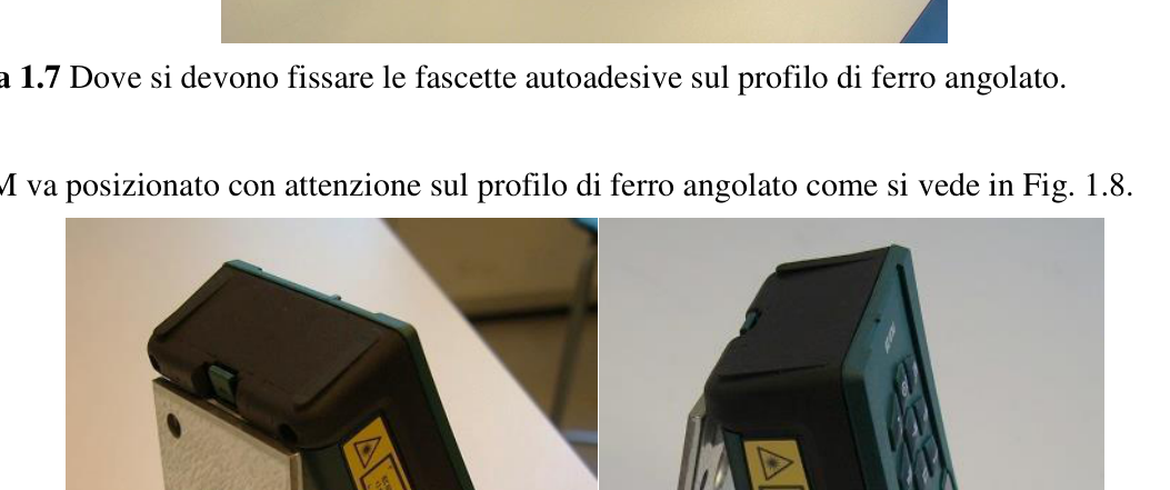
Il LDM va posizionato con attenzione sul profilo di ferro angolato come si vede in Fig. 1.8.
Figura 1.8 Come si deve sistemare il misuratore laser di distanze sul profilo di ferro angolat
p.1 — Materiali per l’esperimento, etichettati A-G
p.3 — Pulsanti del misuratore laser di distanza
p.3 — Misuratore di distanza laser visto da davanti
p.5 — Schema del cavo a fibra ottica
p.5 — Foltrino e cavo in fibra ottica
p.7 — Strumentazione del profilo in ferro angolato
p.8 — Fissaggio delle fascette al profilo angolato
p.8 — LDM sistemato nel profilo angolato
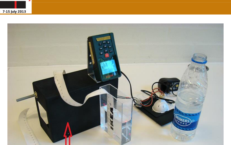
p.9 — Apparato sperimentale montato sulla scatola
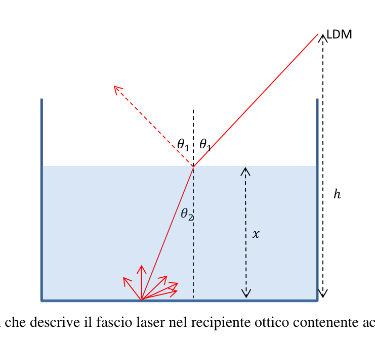
p.10 — Schema del fascio laser nel recipiente con acqua
Topic: Geometric Optics, Wave Optics, Oscillations & Waves Metodi: Snell’s Law, Graph Linearization, Experimental Data Analysis, Ray Tracing Competenze: Experimental Data Analysis, Graph Linearization, Measurement & Instrumentation Objects: — Fonte: Testo (PDF) — p.1 Soluzione: Soluzioni (PDF)
Speed of light E1
Page 1 of 10
Note: All results of measurements and calculated values must be reported in units The SI with the appropriate number of significant figures. The experimental uncertainties are The Commission shall adopt the following measures:
1.0 Introduction to the text Experiments with a laser distance measurement (LDM)
Figure 1.1 Some materials for the experiment A: Laser distance measurement B: fibre optic cable (about 1 m) C: Self-adhesive black holes with a hole D: paper meter E: adhesive tape F: Scissors G: black box cover A laser distance measurement (LDM, see Fig. 1.2 and Fig. 1.3) consists of an issuer and an The receiver. The emitter is a laser diode that emits a modulated laser beam, i.e. a laser beam at the
Speed of light E1
Page 2 of 10
The amplitude varies with a very high frequency. When the laser beam hits an object, the light is It’s reflected in all directions by the laser stain. Some of the light is returned to the receiver of the instrument which is placed immediately next to the issuer. The objective of the instrument is to It focuses on the laser spot and receives the light back from it. The electronics of the instrument measuring the time difference in the modulation of the light signal received The one that was issued. The delay of modulation is exactly the time it takes for light to the number of units of the test chemical used in the test chemical. The measured time is then converted to distance y through the formula
This value of is displayed on the instrument screen. Here’s the one. speed of light. The constant depends on the configuration of the instrument; the instrument is the distance from the rear or front of the instrument can be measured. When the The laser distance meter is turned on, it is set to measure the distance from the back. This configuration shall be maintained during all measurements. Due to the parallel error, the LDM cannot measure a distance less than 5 cm. The distance maximum measurable distance is approximately 25 m. The shape of the instrument is such that it is the part The rear and front axles are perpendicular to the laser beam. When the instrument is supported On the table, the polarization is vertical (perpendicular to the screen). The diode laser is class 2 with a power of less than 1 mW and a wavelength of 635 nm. The measurement uncertainty indicated by the manufacturer is mm. Attention: The diode laser of the instrument can damage vision. Don ‘t look in the beam . laser and don’t project it into other people’s eyes!
The LDM configuration The previous formula for distance assumes that light propagates at speed . For the The experimental accuracy level does not require a distinction between the speed of light in the vacuum and in air, since the refractive index for dry air at atmospheric pressure and temperature Environment is good .
Speed of light E1
Page 3 of 10
Figure 1.2 The six unlabeled buttons are not relevant to the measurement (they are used to calculate the The Commission shall adopt implementing acts in accordance with Article 21 of this Regulation. The key buttons are: A: on/off B: switch to alternate measurement from the rear or front of the instrument C: indicator of the front/rear measurement D: laser powering / start of measurement E: Continuous measurement F: Continuous measurement indicator
Figure 1.3 The laser distance gauge as seen from the front A: Receiver: optics focused on the laser spot B: emitter: do not look into the laser beam!
Speed of light E1
Page 4 of 10
1.1 Measurement with a laser distance gauge The instrument shall take a measurement by pressing the D button, see Fig. 1.2.
1.1a Use the LDM to measure the distance from the top of the table to the floor. Indication The experimental uncertainty . Show how you measure with a drawing. 0.4
Speed of light E1
Page 5 of 10
1.2 Experiment with a fibre optic cable
Figure 1.4 Schematic representation of a fiber optic cable. You were given a fiber optic cable approximately 1 m long and approximately 1 m in diameter. di 2 mm. The cable consists of two optical materials. The one in the centre (approximately 1 in diameter) mm) is made of a plastic material with a high refractive index. It is surrounded by a a coating material consisting of a different plastic material with a refractive index The product is a slightly smaller product, which is coated with a protective black plastic layer. The central material and the coating acts as a guide for the light entering the cable. In fact, the interface between the two causes a total reflection that prevents the light from leaving the central material. This occurs until the angle of incidence is greater than the angle of limit for the total reflection. The Light Therefore, it will remain inside the central material of the fibre even if the fibre is curved, As long as it’s not too much. The LDM must now be configured for continuous measurement (pulsant E, see Fig. 1.2), So the display indicator is updated approximately once a second. Il LDM will automatically shut down after a few minutes. It can be reactivated by pressing the button Red at the start. Carefully and gently cover the optical area of the LDM receiver with a black felt (the other is The test is performed in a 2 mm diameter hole (see Fig. A). 1.3). The adhesive side of the The fern must be gently pressed against the lens. Insert a fiber optic cable of length in the flap hole so as to make it touch the optical of the detector, see Fig. 1.5.
Figure 1.5 (a) Feltrin and fibre cable. (b) How to mount the fiber optic cable.
Speed of light E1
Page 6 of 10
The other end of the cable shall be held against the emitter so that the latter touches the The fiber in the middle of the laser beam. Now read the value of the instrument. Scissors placed on The device must be used to cut the fibre cable at different lengths . Attention: think and plan very carefully for cutting the fibre optic cable, as it does not You will be given more of it! Note also that the LDM display may display the thermometer icon after a little continuous operation time due to overheating of the electronics. In This case turns off the LDM for a while to cool the instrument.
1.2a Measures the corresponding values of e . Put your values back on a table. Trace a graph of the function of . 1.8 1.2b Use the graph to find the refractive index of the central fiber material The optical. Calculates the speed of light in the central material of the fiber optic cable. 1.2
Speed of light E1
Page 7 of 10
1.3 Laser distance measurement at a certain angle from the vertical In this part of the experiment, the instrumentation shown in Fig. 1 is available to you. 1.6.
Figure 1.6 Instrumentation shown in the figure: A: water optical experimental vessel and paper meter B: Magnets to fix the angled iron profile at the top of the black box. (The magnet is located attached to the angled iron profile.) C: angled iron profile with self-adhesive tape D: Self-adhesive tape
Remove the black felt tampon from the lens. The LDM shall be mounted as follows: Self-adhesive fasteners on the angled iron profile as shown in Figure 1.7 in point A.
Speed of light E1
Page 8 of 10
Figure 1.7 Where the self-adhesive bands must be fixed to the angled iron profile.
The LDM shall be carefully positioned on the angled iron profile as shown in Fig. 1.8.
Figure 1.8 How to set the laser distance gauge on the angled iron profile
p.1 Materials for the experiment, labelled A-G
The following information shall be provided:
**p.3 ** Laser distance gauge as seen from the front
The following is the list of the types of fibre optic cables:
**p.5 ** Folding and cable of optical fibre
The following is the list of the types of equipment used:
The following table shows the results of the tests:
p.8 LDM set to the angled profile
Test apparatus mounted on the box
p.10 Laser beam pattern in the water container
Topic: Geometric Optics, Wave Optics, Oscillations & Waves Metodi: Snell’s Law, Graph Linearization, Experimental Data Analysis, Ray Tracing Competenze: Experimental Data Analysis, Graph Linearization, Measurement & Instrumentation Objects: — Fonte: Testo (PDF) — p.1 Soluzione: Soluzioni (PDF)