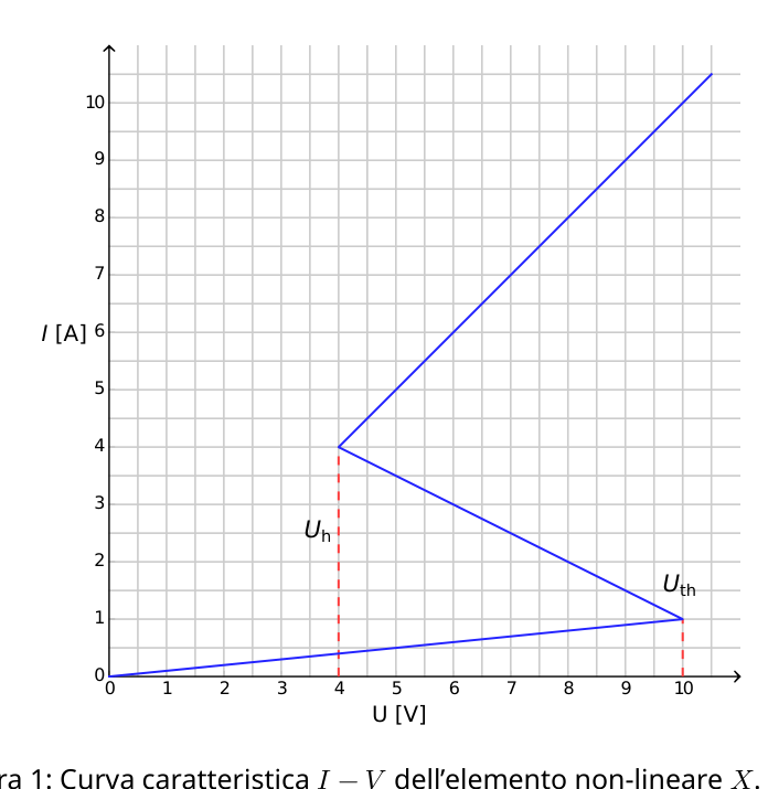
Theory Italiano (Italy) Q2-1 Dinamica non-lineare nei circuiti elettrici (10 punti) Per favore, leggi le istruzioni di carattere generale nella busta a parte prima di iniziare a lavorare su questo problema. Introduzione Elementi semiconduttori non-lineari bistabili (per es. i thyristor) sono ampiamente usati in elettronica come interruttori e generatori di oscillazioni elettromagnetiche. Il principale campo di applicazione dei thyristor è nel controllo delle correnti alternate in circuiti elettronici di potenza, per esempio per la conversione di corrente alternata (AC) in corrente continua (DC) con potenze dell’ordine del megawatt. Elementi bistabili possono servire anche per modellizzare fenomeni di auto-organizzazione in fisica (la parte B del problema si riferisce a questo argomento), in biologia (v. parte C) e in altri campi della moderna scienza non lineare. Obbiettivi Studiare le instabilità e la dinamica non banale di circuiti che contengono elementi aventi una curva caratteristica lineare. Scoprire possibili applicazioni di tali circuiti in ingegneria e nella modellizzazione di sistemi biologici. Parte A. Stati stazionari e instabilità (3 punti) La figura 1 mostra la curva caratteristica , detta ad S, di un elemento non-lineare X. Nell’intervallo di d.d.p. tra Uh = 4.00 V (tensione di mantenimento - holding voltage) e Uth = 10.0 V (tensione di soglia
- threshold voltage) questa curva caratteristica una funzione a più valori. Per semplicità il grafico di figura 1 è stata scelto come una curva non lineare ”a tratti” (ogni ramo è costituito da un segmento di retta). In particolare il ramo più in alto appartiene ad una retta passante per l’origine. Questa approssimazione dà una buona descrizione di un thyristor reale.
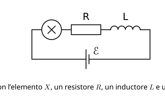
Theory Italiano (Italy) Q2-2 0 1 2 3 4 5 6 7 8 9 10 U [V] 0 1 2 3 4 5 6 7 8 9 10 Uh Uth I [A] Figura 1: Curva caratteristica non-lineare X. A.1 Usando il grafico, determina la resistenza Ron dell’elemento Xnel ramo superiore della curva caratteristica , e Roff nel ramo inferiore, rispettivamente. Il ramo intermedio è descritto dall’equazione I= I0 Rint . (1) Trovare il valore dei parametri I0 e Rint. 0.4pt L’elemento Xè collegato in serie (v. figura 2) con il resistore R, l’induttore Le un generatore ideale di d.d.p. E. Si dice che il circuito è in uno stato stazionario se la corrente è costante nel tempo, I(t) = const. E R L Figura 2: Circuito con l’elemento X, un resistore R, un inductore Le un generatore di d.d.p. E. A.2 Quali sono i possibili numeri di stati stazionari che il circuito di figura 2 può avere per un dato valore Edella d.d.p. del generatore e per R= 3.00 ? Come cambia la risposta per R= 1.00 ? 1pt
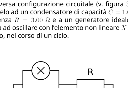
Theory Italiano (Italy) Q2-3 A.3 Sia R= 3.00 , L= 1.00 μH ed E= 15.0 V nel circuito mostrato in figura 2. Determina il valore della corrente Istationary e della d.d.p. Vstationary ai capi dell’elemento non-lineare X, nello stato stazionario. 0.6pt Il circuito di figura 2 è in uno stato stazionario con I(t) = Istationary. Questo stato stazionario è detto stabile se, a seguito di un piccolo spostamento (la corrente cresce o decresce), la corrente torna al valore dello stato stazionario. Se invece il sistema tende ad allontanarsi ulteriormente dallo stato stazionario, si dice che questo è instabile. A.4 Usa i valori numerici della domanda A.3 e studia la stabilità dello stato stazionario con I(t) = Istationary. E’ stabile o instabile? 1pt Parte B. Elementi bistabili non-lineari in fisica: trasmettitore radio (5 punti) Consideriamo adesso una diversa configurazione circuitale (v. figura 3). Questa volta l’elemento nonlineare Xè collegato in parallelo ad un condensatore di capacità C= 1.00 μF. Questo blocco è collegato in serie al resistore di resistenza R= 3.00 e a un generatore ideale di d.d.p. costante E= 15.0 V. Viene fuori che il circuito inizia ad oscillare con l’elemento non lineare Xche salta da un ramo della curva caratteristica un altro, nel corso di un ciclo. C E R Figura 3: Circuito con l’elemento X, il condensatore C, il resistore Re il generatore di d.d.p. E. B.1 Traccia il ciclo dell’oscillazione sul grafico della curva caratteristica , precisando il suo verso (orario o antiorario). Giustifica la tua risposta con equazioni e schizzi. 1.8pt B.2 Trova le espressioni dei tempi t1 e t2 durante i quali il sistema si trova in ciascuno dei due rami della curva caratteristica il periodo di un’oscillazione. Determina i loro valoci numerici. Trova il valore numerico del periodo di oscillazione Tfacendo l’ipotesi che i tempi necessari a saltare da un ramo ad un altro della curva trascurabili. 1.9pt B.3 Stima la potenza media Pdissipata nell’elemento non-lineare nel corso di un’oscillazione. E’ sufficiente dare l’ordine di grandezza. 0.7pt
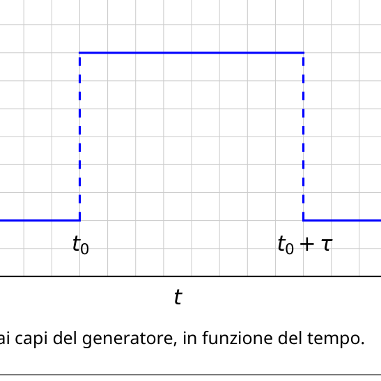
Theory Italiano (Italy) Q2-4 Il circuito di figura 3 viene usato per costruire una trasmittente radio. Per questo scopo l’elemento Xviene connesso ad un’estremità di un’antenna lineare (un lungo filo rettilineo) di lunghezza s. L’altra estremità del filo è libera. Nell’antenna si forma un’onda elettromagnetica. La velocità dell’onda elettromagnetica lungo l’antenna è la stessa del vuoto. Il trasmettitore usa l’armonica principale del sistema che ha il periodo Tdella domanda B.2. B.4 Qual è il valore ottimale di sassumendo che esso non possa superare la lunghezza di 1 km? 0.6pt Parte C. Elementi bistabili non-lineari in biologia: il neuristor (2 punti) In questa parte del problema consideriamo un’applicazione degli elementi bistabili non-lineari per modellizzare dei processi biologici. Un neurone del cervello umano ha questa proprietà: quando viene eccitato da un segnale esterno, effettua una singola oscillazione e torna nel suo stato iniziale. Questa caratteristica è chiamata eccitabilità. A causa di questa proprietà gli impulsi si possono propagare nella rete di neuroni accoppiati che formano i sistemi nervosi. Un chip semiconduttore progettato per simulare l’eccitabilità e la propagazione di un impulso è chiamato neuristor (da neurone e transistor). Cerchiamo di modellizzare un semplice neuristor usando un circuito che include l’elemento non lineare Xche abbiamo studiato precedentemente. Per questo la d.d.p. Enel circuito di figura 3 viene diminuita al valore = 12.0 V. Le oscillazioni si interrompono e il sistema raggiunge uno stato stazionario. In seguito la d.d.p. viene improvvisamente riportata al valore E= 15.0 V, e dopo un intervallo di tempo τ (con τ< T) viene fissata di nuovo al valore (v. figura 4). Si vede che esiste un certo valore critico τcrit., e che il sistema mostra un diverso comportamento a seconda che sia τ< τcrit oppure τ> τcrit. t 11 12 13 14 15 16 E t0 t0 + Figura 4: d.d.p. ai capi del generatore, in funzione del tempo. C.1 Fai uno schizzo del grafico della corrente IX(t) che attraversa l’elemento nonlineare Xnel caso τ< τcrit e nel caso τ> τcrit. 1.2pt
Theory Italiano (Italy) Q2-5 C.2 Trova l’espressione e il valore numerico del tempo critico τcrit per il quale il comportamento cambia. 0.6pt C.3 Il circuito con τ= 1.00 s rappresenta un neuristor? 0.2pt
p.2 — Curva caratteristica I-V elemento non-lineare X
p.2 — Circuito con elemento X, R, L, generatore
p.3 — Circuito con elemento X, condensatore C, resistore R
p.4 — Andamento temporale della tensione del generatore
Topic: Circuits, Oscillations & Waves, Electromagnetic Induction Metodi: Kirchhoff’s Laws, Differential Equations, Simple Harmonic Motion Analysis, Wave Equation Competenze: Mathematical Modeling, Diagrammatic Reasoning, Physical Reasoning Objects: Resistor, Inductor, Capacitor, Battery, Wire Fonte: Testo (PDF) — p.1 Soluzione: Soluzioni (PDF)
Theory Italian (Italy) Q2-1 Non-linear dynamics in electrical circuits (10 points) Please read the general instructions in the separate envelope before you start working on I’m not going to let you know. The Commission Other, of a kind used for the manufacture of electrical equipment Thyristor (s) are widely used in electronics as switches and generators of electromagnetic oscillations. The main scope The thyristor is in the control of alternating currents in power electronic circuits, for example for the conversion of alternating current (AC) to direct current (DC) with power of the order of megawatt. The two-dimensional elements can also be used to model self-organizing phenomena in physics (the The problem is that part B of the problem relates to this topic, in biology (see. (c) and in other fields of modern nonlinear science. Objectives Studying the instability and non-trivial dynamics of circuits containing curved elements caratteristica lineare. Discover possible applications of such circuits in engineering and biological system modelling. Part A. Stabilisation and instability (3 points) Figure 1 shows the characteristic curve , called S, of a non-linear element X. In the interval di d.d.p. between Uh = 4.00 V (maintenance voltage - holding voltage) and Uth = 10.0 V (threshold voltage)
- threshold voltage) this curve characteristic a multi-valued function. For simplicity the graph Figure 1 has been chosen as a non-linear curve a tracts (each branch consists of a segment of I’m going to be a little bit more careful. In particular, the uppermost branch belongs to a straight line passing through the origin. This approximation gives a good description of a real thyristor.
Theory Italian (Italy) Q2-2 0 1 2 3 4 5 6 7 8 9 10 U [V] 0 1 2 3 4 5 6 7 8 9 10 Uh Other I [A] Figure 1: Characteristic curve non-linear X. A.1 Using the graph, it determines the resistance of the Ron of the X element in the upper branch of the characteristic curve , and Roff in the lower branch, respectively. The intermediate branch is described by the equation I= I0 Other . (1) Find the value of the parameters I0 and Rint. 0.4pt The X element is connected in series (see. Figure 2 shows that with the resistor R, the inductor Le is an ideal generator for d.d.p. E. It is said that the circuit is in a stationary state if the current is constant over time, I(t) = const. E R L Figure 2: Circuit with X element, a resistor R, an inductor Le and a power generator E. A.2 What are the possible numbers of stationary states that the circuit in Figure 2 can have for a given value Edella d.d.p. of the generator and for R= 3.00 ? How does the answer change for R=1.00 ? 1pt
Theory Italian (Italy) Q2-3 A.3 Sia R= 3.00 , L= 1.00 μH ed E= 15.0 V nel circuito mostrato in figura 2. Determine the value of the current stationary and the d.d.p. Vstationary to the heads of the element nonlinear X, in the stationary state. 0.6pt The circuit in Figure 2 is in a stationary state with I(t) = Istationary. This stationary state is said to be stable if, following a small shift (the current increases or The current returns to the stationary state value. If the system tends to drift away Further down the steady state, it is said that this is unstable. A.4 Use the numerical values of the A.3 question and study the stability of the state The following is the list of the following: Is it stable or unstable? 1pt Part B. Non-linear biastable elements in physics: radio transmitter (5 points) Consider now a different circuit configuration (v. The Commission shall adopt implementing acts in accordance with Article 21 of this Regulation. This time the nonlinear element X is connected in parallel to a capacitor C=1.00 μF. This block is connected in series with resistor R= 3,00 and an ideal d.d.p. generator. The value of the product shall be the same as the value of the product. It turns out that the circuit starts to oscillate with the nonlinear element X that jumps from a branch of the curve The characteristic is another, over a cycle. C E R Figure 3: Circuit with element X, capacitor C, resistor Re and power generator E. B.1 Trace the oscillation cycle on the graph of the characteristic curve , specifying its direction (time or counter-time). Justify your answer with equations and sketches. 1.8pt B.2 Find the expressions of the times t1 and t2 during which the system is located in each The time of one oscillation of the two branches of the characteristic curve . Determine their numerical values. Find the numerical value of the oscillation period Assuming that the time required to jump from one branch to another della curva trascurabili. 1.9pt B.3 Estimate the average power lost in the nonlinear element during the The result is a slight oscillation. It is sufficient to give the order of magnitude. 0.7pt
Theory Italian (Italy) Q2-4 The circuit in Figure 3 is used to build a radio transmitter. For this purpose, the Xviene element connected to an end of a linear antenna (a long straight wire) of s length. The other end of the wire is free. An electromagnetic wave is formed in the antenna. La The speed of the electromagnetic wave along the antenna is the same as that of the vacuum. The transmitter uses the harmonic The main system that has the period T is application B.2. B.4 What is the optimal value of assessing that it cannot exceed the a mile in length? 0.6pt Part C. Nonlinear biotable elements in biology: the neuristor (2 points) In this part of the problem we consider the application of nonlinear bistable elements to model biological processes. A neuron in the human brain has this property: When excited by an external signal, it makes a single oscillation and returns to its original state. This is called excitement. Because of this property, pulses can propagate through the network. of paired neurons that form the nervous system. A semiconductor chip designed to simulate The excitation and propagation of a pulse is called a neuristor (from neuron and transistor). We’re trying to model a simple neuristor using a circuit that includes the nonlinear element We’ve studied this before. That’s why the D.D.P. The circuit in Figure 3 is decreased The value of the test chemical is = 12,0 V. The oscillations stop and the system reaches a stationary state. In Following the D.D.P. is suddenly returned to E= 15.0 V, and after a time interval τ (with τ< T) is set again to (v. The Commission shall adopt implementing acts in accordance with Article 4 (1) of this Regulation. It is seen that there is a certain critical value τcrit., and that the system shows a different behaviour in The second is whether it is τ< τcrit or τ> τcrit. t 11 12 13 14 15 16 E t0 t0 + Figure 4: D.d.p. The time of the day depends on the time of day. C.1 Draw a diagram of the current IX(t) that passes through the nonlinear element X in the case τ< τcrit and τ> τcrit. 1.2pt
Theory Italian (Italy) Q2-5 C.2 Find the expression and numerical value of the critical time for which the The behavior changes. 0.6pt C.3 The circuit with τ=1.00 s is a neuristor? 0.2pt
p.2 — Curva caratteristica I-V elemento non-lineare X
p.2 — Circuito con elemento X, R, L, generatore
p.3 — Circuito con elemento X, condensatore C, resistore R
p.4 — Andamento temporale della tensione del generatore
Topic: Circuits, Oscillations & Waves, Electromagnetic Induction Metodi: Kirchhoff’s Laws, Differential Equations, Simple Harmonic Motion Analysis, Wave Equation Competenze: Mathematical Modeling, Diagrammatic Reasoning, Physical Reasoning Objects: Resistor, Inductor, Capacitor, Battery, Wire Fonte: Testo (PDF) — p.1 Soluzione: Soluzioni (PDF)